Axial modification method of involute straight toothed spur gear pair and special parametric CAD (computer aided design) system matched with axial modification method

A technology of spur gears and involutes, applied in geometric CAD, electrical digital data processing, design optimization/simulation, etc., can solve the problem of meshing performance analysis and Problems such as performance evaluation, inability to accurately calculate the strength of the modified gear, and difficulty in optimizing the structure of the modified gear, etc., to achieve high-tech economy, practicality, strong versatility, and the effect of ensuring stability and reliability

Active Publication Date: 2016-12-07
SHANDONG UNIV OF SCI & TECH
View PDF4 Cites 11 Cited by
  • Summary
  • Abstract
  • Description
  • Claims
  • Application Information

AI Technical Summary

Problems solved by technology

Since the strength of the modified gear cannot be accurately calculated, only empirical formulas can be used for approximate calculations, and it is difficult to optimize the structure of the modified gear
With the maturity and development of CAD technology, many technicians have conducted research on the modification method and simulation method of involute cylindrical gear transmission with modified tooth direction, which provides conditions for accurate modeling and accurate performance analysis of modified gears. But so far, it has not been able to solve the problem of how to determine the appropriate tooth shape modification curve for different working conditions, nor can it effectively solve the meshing performance analysis and performance evaluation of the tooth shape modified involute cylindrical gear pair.

Method used


Image

  • Axial modification method of involute straight toothed spur gear pair and special parametric CAD (computer aided design) system matched with axial modification method
  • Axial modification method of involute straight toothed spur gear pair and special parametric CAD (computer aided design) system matched with axial modification method
  • Axial modification method of involute straight toothed spur gear pair and special parametric CAD (computer aided design) system matched with axial modification method

Examples


Embodiment Construction

[0102] In the following, the present invention will be described in detail by taking a pair of involute spur gear pairs that need to be used under two working conditions as an embodiment.

[0103] Description: In the following examples, the original parameters of a pair of involute spur gear pairs that need to be used in two working conditions are shown in Table 1.

[0104] Table 1 Original parameters of involute spur gear pair

[0105]

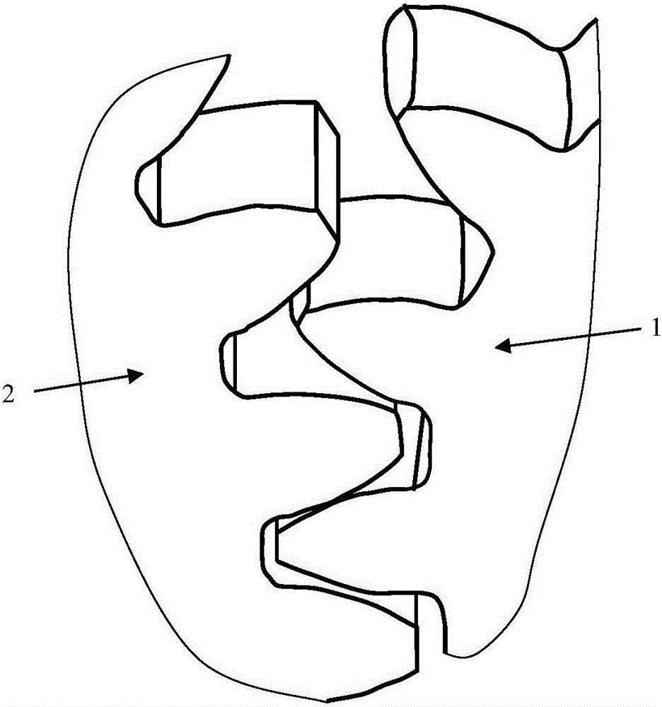
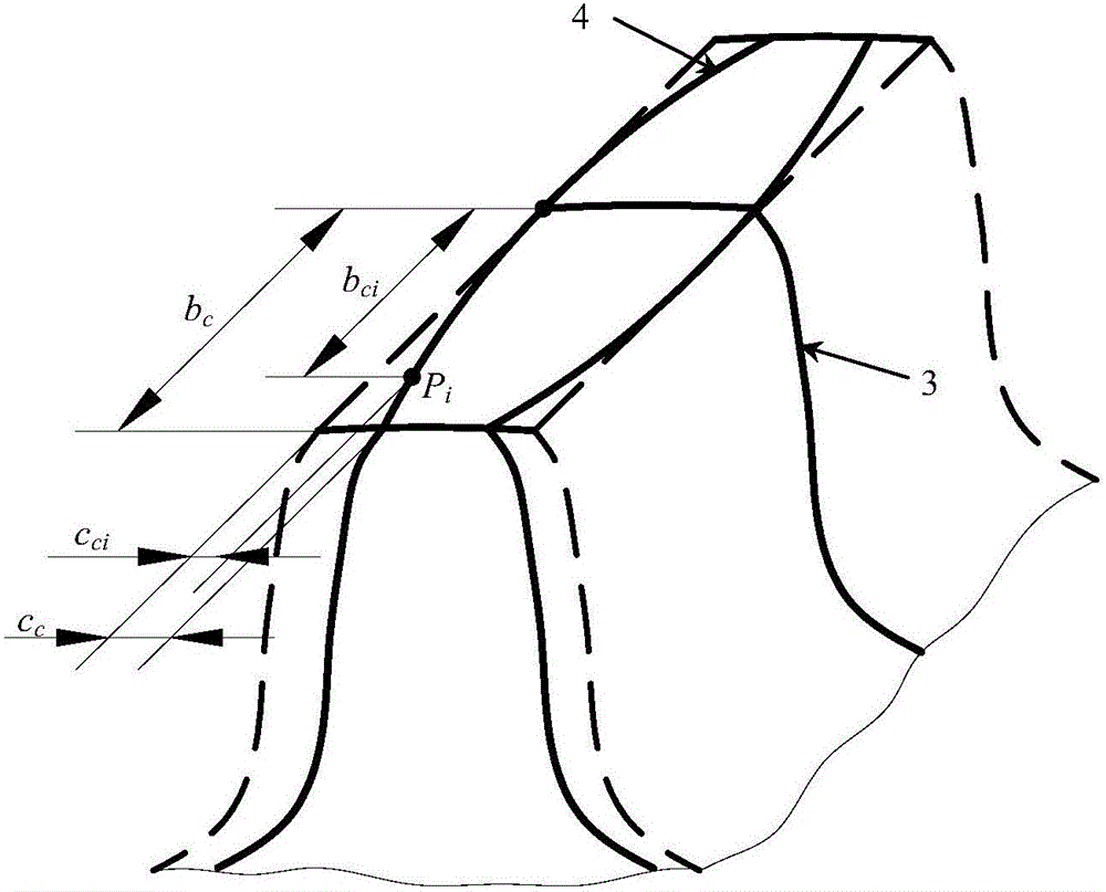
[0106] like figure 1 As shown in the figure, a method for modifying the tooth direction of an involute spur gear pair, only one gear in the gear pair is modified, the gear is named as gear A; the other gear in the gear pair is named as Gear B; it is characterized in that the compound tooth direction modification curve of the above-mentioned gear A satisfies the following general formula (1):

[0107] c c i = αc c ...


PUM


Abstract

The invention discloses an axial modification method of an involute straight toothed spur gear pair and a special parametric CAD (computer aided design) system matched with the axial modification method. The axial modification method of the involute straight toothed spur gear pair comprises main steps as follows: universal composite axial modification curves are established, simulated axial modification of gears is performed by means of the obtained multiple composite axial modification curves one by one with an orthogonal test method, and a simulation transmission test is performed, so that the composite axial modification curve corresponding to the optimal simulation transmission test result is screened out. According to the special parametric CAD system matched with the axial modification method, the involute straight toothed spur gear pair after axial modification is treated in processes including solid modeling, meshing simulation analysis, extraction of meshing performance of an axial modification gear pair and the like and then is blended into the system, and the system has complete functions, is convenient to use and can be efficiently used for aided design for research and development of the gears. The axial modification method is high in universality and stable and reliable in modification quality; the CAD system has the complete functions and is simple to operate.

Description

technical field [0001] The invention relates to a tooth direction modification method and a parametric CAD system of a gear pair, in particular to a tooth direction modification method of an involute spur gear pair and a special parametric CAD system matched with it. Background technique [0002] During the use of the involute spur gear pair, due to the influence of the installation error of the transmission mechanism or the bending deformation of the gear after being loaded, phenomena such as eccentric load and stress concentration at the tooth end often occur along the tooth direction of the gear. It affects the service life of the gear pair, so it is necessary to modify the tooth direction. [0003] The modification operation of the involute cylindrical gear is complicated, which not only involves the gear structure, but also involves many factors such as the manufacturing and assembly accuracy of the gear, the support method on the shaft, the nature of the load, and the ...

Claims


Application Information

Patent Timeline
Patent Type & Authority Applications(China)
IPC IPC(8): G06F17/50
CPCG06F30/17G06F30/20
Inventor 李学艺王宁宁万丽荣曾庆良张鑫王坤张国鹏
Owner SHANDONG UNIV OF SCI & TECH
Why Eureka
Try Eureka