Fuse for wind power protection and replacement method of fusing feedback device of fuse
A technology of feedback devices and fuses, which is applied in the direction of emergency protection devices, circuits, electrical components, etc., can solve the problems that electric workers cannot obtain information feedback in time, troubles, etc., achieve quick and convenient assembly, smooth contact surface, and improve maintenance efficiency Effect
- Summary
- Abstract
- Description
- Claims
- Application Information
AI Technical Summary
Problems solved by technology
Method used
Image
Examples
Embodiment 1
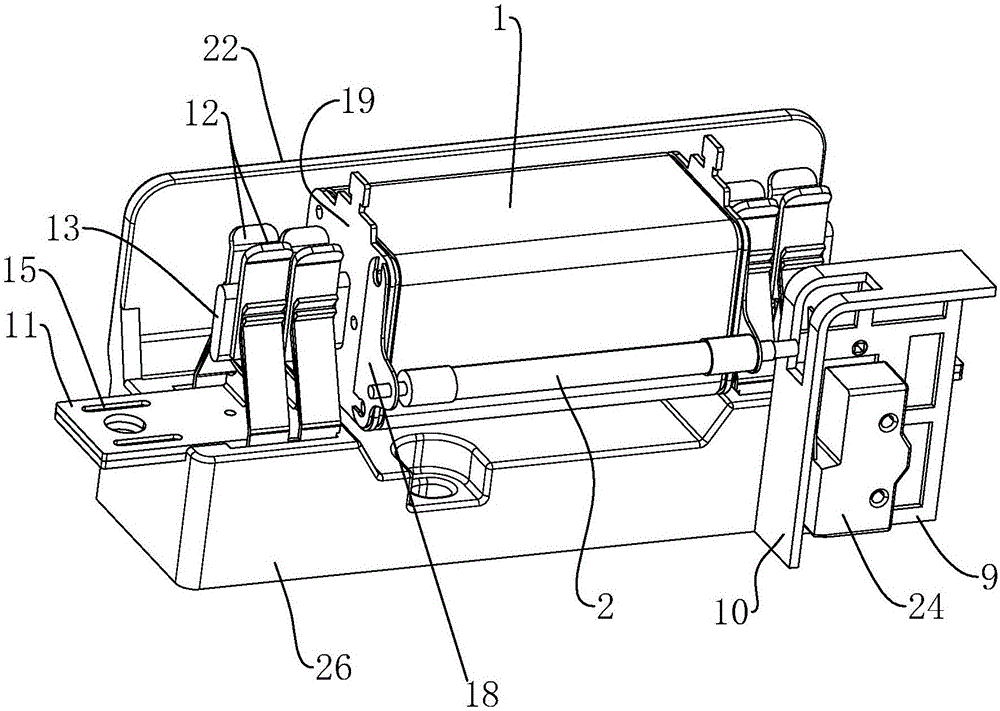
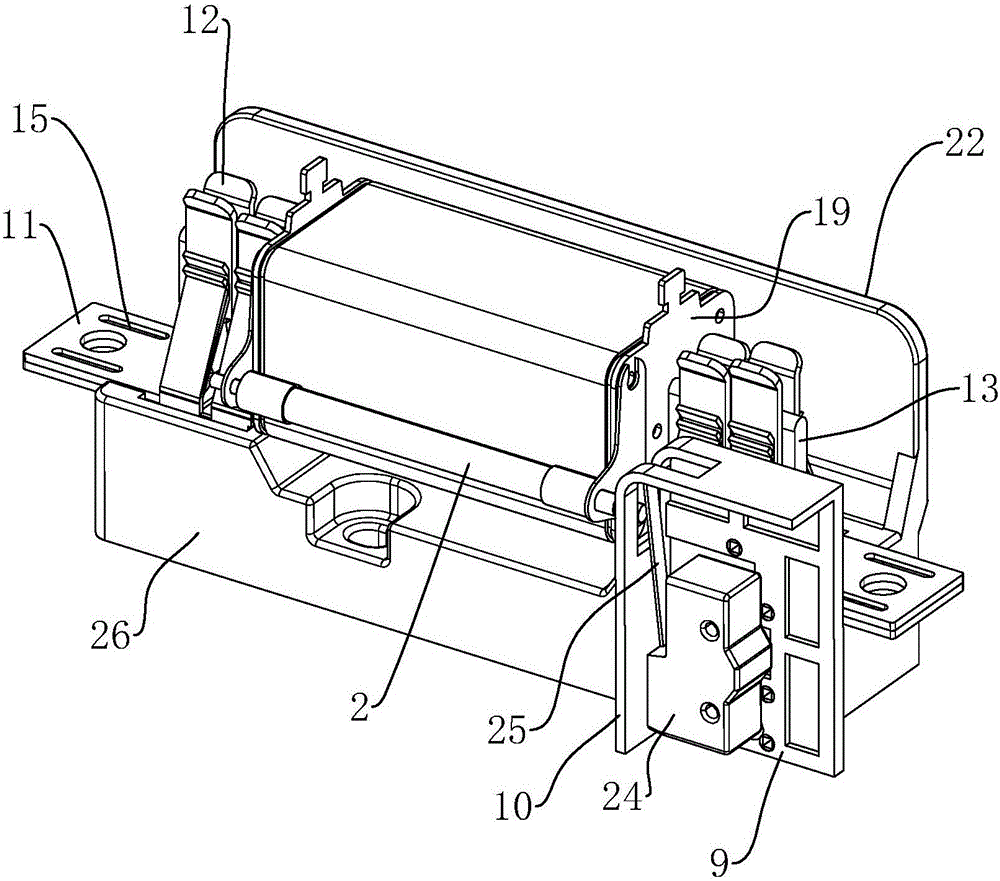
[0044] Embodiment one: if figure 1 and figure 2 , a fuse for wind power protection, including a mounting base 26 for installing a fuse body 1, and a fuse feedback device is provided on the mounting base 26. The fusing feedback device includes a trigger 2, and brackets 18 are installed on both sides of the trigger 2, and the brackets 18 are connected with the fuse body 1 by screws. The side of the mounting base 26 close to the fuse 1 is provided with an arc shield 22 , the height of the arc shield 22 is greater than that of the fuse 1 , and when the fuse 1 is inserted or removed, the arc shield 22 prevents the arc from spreading.
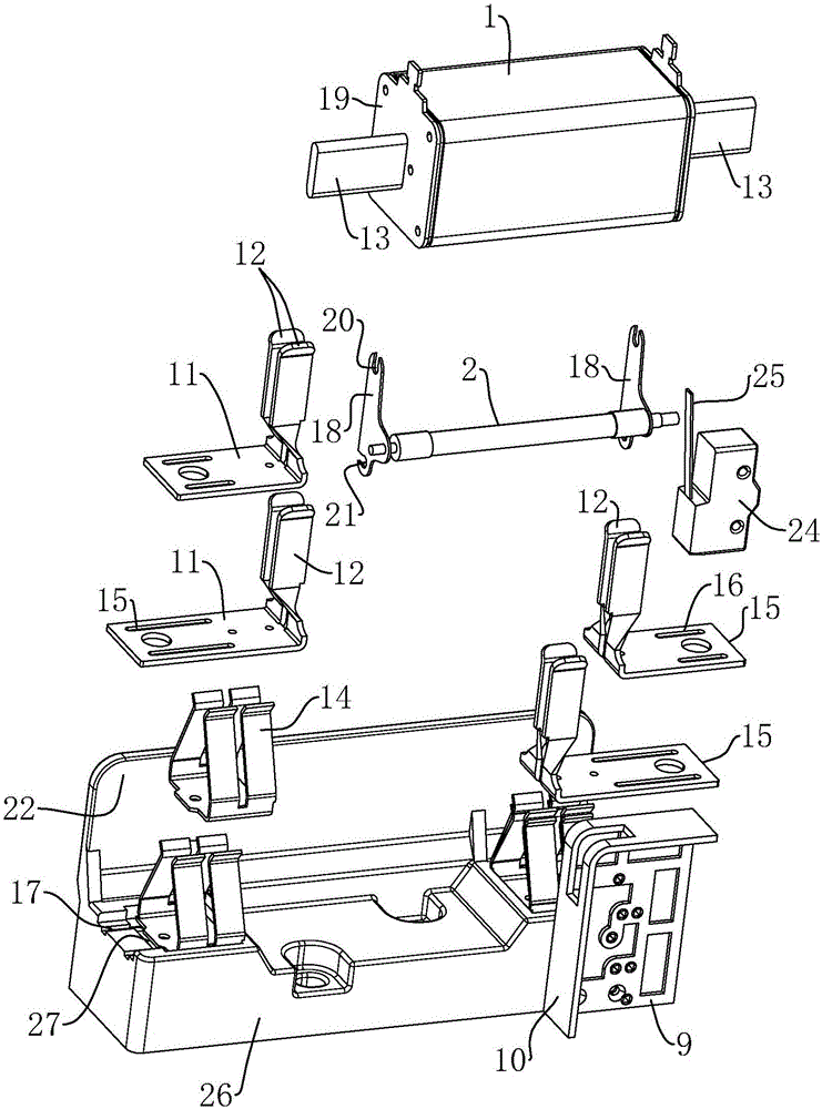
[0045] combine image 3 and Figure 6 , both sides of the mounting base 26 are provided with positioning grooves 27, and the positioning grooves 27 are embedded with a clamping contact 11. The clamping contacts 11 include two pieces of contacts 12, and the positions of the two positioning grooves 27 have been determined, so The two clamping cont...
Embodiment 2
[0051] Embodiment 2: A fuse for wind power protection, including a mounting seat 26 for mounting the fuse body 1 , and a fuse feedback device is provided on the mounting seat 26 . The fusing feedback device includes a trigger 2, a linkage mechanism and an interaction mechanism.
[0052] Such as Figure 7 The trigger 2 is provided with a fuse 4 and a striker 3 connected to the fuse 4. The trigger 2 is also provided with a first spring 5. One end of the first spring 5 abuts against the inner wall of the trigger 2, and the other end Sleeved on the impact piece 3, the impact piece 3 is in the shape of a stepped shaft, so the first spring 5 can be engaged with the shoulder of the impact piece 3, and the two form a relative restraint to be installed together; when the fuse 4 is tightened, the impact piece 3 Push the first spring 5 to move to the left so that the first spring 5 is in a compressed state, so the first spring 5 retains elastic potential energy. The fuse 4 passes throu...
Embodiment 3
[0054] Embodiment 3: A replacement method for the fusing feedback device of Embodiment 1 or Embodiment 2, comprising the following steps:
[0055] Step 1: Remove the old fuse 1 and the old fuse feedback device, and take the fuse 1 and fuse feedback device to be used;
[0056] Step 2: Take two brackets 18 to cooperate with the two ends of the trigger 2 respectively, take screws and penetrate into the first connecting groove 20 on the brackets 18, and pre-install the brackets 18 and the cover plates 19 on both sides of the fuse body 1 through two screws. fixed;
[0057] Step 3: Rotate the trigger 2 around the axis of the two screws, and when the second connection groove 21 is rotated to the matching position of the cover plate 19 with the rotation of the bracket 18, then take the screw and insert it into the second connection groove 21, and tighten all the screws to complete the assembly of the trigger 2 and the fuse 1;
[0058] Step 4: Take the fuse body 1 assembled in step 3...
PUM
 Abstract
Description
Claims
Application Information
 - R&D
- Intellectual Property
- Life Sciences
- Materials
- Tech Scout
- Unparalleled Data Quality
- Higher Quality Content
- 60% Fewer Hallucinations
Browse by: Latest US Patents, China's latest patents, Technical Efficacy Thesaurus, Application Domain, Technology Topic, Popular Technical Reports.
© 2025 PatSnap. All rights reserved.Legal|Privacy policy|Modern Slavery Act Transparency Statement|Sitemap|About US| Contact US: help@patsnap.com


