Sharply Bend Rectangular Waveguide Based on Supertransmitting Slot Diaphragm
A rectangular waveguide and diaphragm technology, applied in the microwave field, can solve the problems of large volume and complex waveguide structure, and achieve the effect of reducing the volume and simplifying the structure.
- Summary
- Abstract
- Description
- Claims
- Application Information
AI Technical Summary
Problems solved by technology
Method used
Image
Examples
Embodiment 1
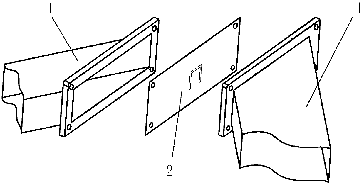
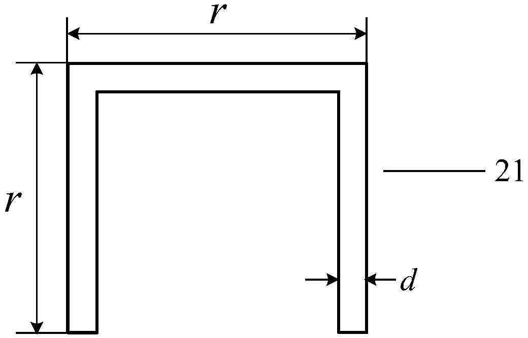
[0029] refer to figure 1 , this embodiment includes a sharply bent rectangular waveguide, the sharply bent rectangular waveguide adopts an H-surface bent rectangular waveguide, which is formed by splicing two symmetrical waveguide structures 1, and the rectangular waveguide is 22.86mm wide and 10.16mm high , a standard WR90 waveguide with a single-mode transmission frequency range of 8.2-12.4GHz. One end of the waveguide structure 1 is provided with a connecting flange, and the plane where the connecting flange is located forms an inclination angle with the cross-section of the waveguide, and is inclined to the direction of the narrow side of the cross-section of the waveguide. The supertransmission membrane 2 is spliced between two symmetrical waveguide structures 1, and the bending angle of the bent rectangular waveguide formed by fixed splicing of the waveguide structure 1 and the supertransmission membrane 2 is 2 of the inclination angle formed by one end of the waveguid...
Embodiment 2
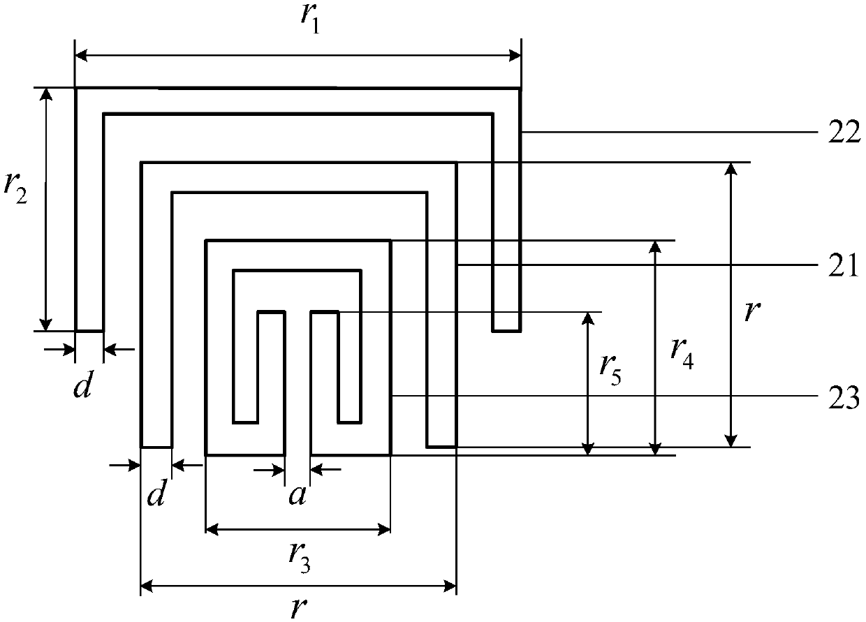
[0032] The present embodiment adopts the same structure as that of Embodiment 1, only the form and size of the opening slit structure are adjusted, and its structure is as follows image 3 shown.
[0033] refer to image 3 , the opening gap structure adopts a C-type multi-frequency composite resonant ring, and the C-type multi-frequency composite resonant ring includes a C-type single-frequency resonant ring 21, a C-type single-frequency resonant outer ring 22 and a C-type single-frequency resonant inner ring Ring 23, forming a three-frequency composite structure composed of three C-type resonant rings, wherein the C-type single-frequency resonant ring 21 is located at the center of the super-transmission diaphragm 2, and at the opening of the C-type single-frequency resonant outer ring 22 Inside, the C-type single-frequency resonant inner ring 23 is located in the opening of the C-type single-frequency resonant ring 21, and in order to meet the frequency requirements while r...
PUM
 Abstract
Description
Claims
Application Information
 - R&D
- Intellectual Property
- Life Sciences
- Materials
- Tech Scout
- Unparalleled Data Quality
- Higher Quality Content
- 60% Fewer Hallucinations
Browse by: Latest US Patents, China's latest patents, Technical Efficacy Thesaurus, Application Domain, Technology Topic, Popular Technical Reports.
© 2025 PatSnap. All rights reserved.Legal|Privacy policy|Modern Slavery Act Transparency Statement|Sitemap|About US| Contact US: help@patsnap.com


