
Combined dynamic continuous-flow control method and device of pseudo-continuous conduction mode single-inductor double-output switching converter

A single-inductor dual-output, pseudo-continuous conduction technology, applied in output power conversion devices, conversion equipment without intermediate conversion to AC, electrical components, etc., can solve the influence of PCCM switching converter characteristics, low converter efficiency, conversion It can avoid problems such as the inability of the device to work stably, so as to avoid the excessively long freewheeling stage, short adjustment time, and improve the light-load efficiency.

Active Publication Date: 2016-12-07
SOUTHWEST JIAOTONG UNIV
View PDF6 Cites 9 Cited by
  • Summary
  • Abstract
  • Description
  • Claims
  • Application Information

AI Technical Summary

Problems solved by technology

But when the equivalent series resistance of the output capacitor is small, the output voltage ripple is non-linear, and the converter cannot work stably
On the other hand, the control of the freewheeling switch also has a great influence on the characteristics of the PCCM switching converter
The freewheeling control of traditional PCCM switching converters adopts the constant-reference-current control (Constant-Reference-Current, CRC) method, which has low converter efficiency under light load conditions

Method used


Image

  • Combined dynamic continuous-flow control method and device of pseudo-continuous conduction mode single-inductor double-output switching converter
  • Combined dynamic continuous-flow control method and device of pseudo-continuous conduction mode single-inductor double-output switching converter
  • Combined dynamic continuous-flow control method and device of pseudo-continuous conduction mode single-inductor double-output switching converter

Examples


Embodiment 1

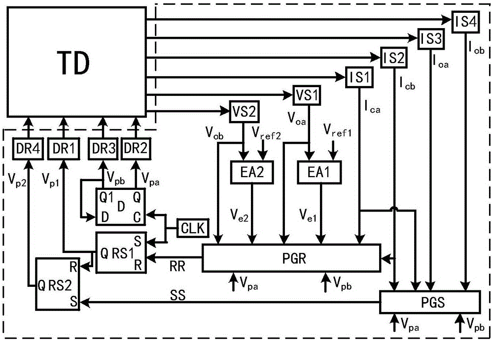
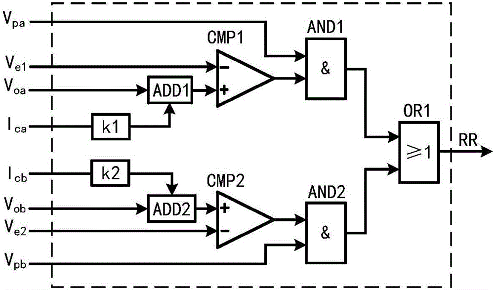
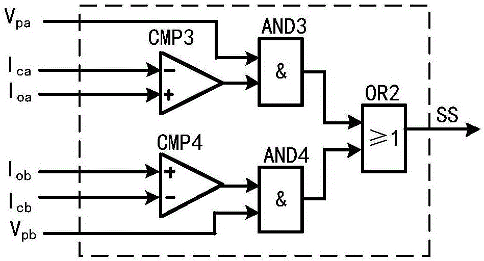
[0029] figure 1 It is shown that a specific embodiment of the present invention is: PCCM single-inductance dual-output switching converter combined dynamic freewheeling control device, mainly composed of the first voltage detection circuit VS1, the second voltage detection circuit VS2, the first current detection circuit IS1, second current detection circuit IS2, third current detection circuit IS3, fourth current detection circuit IS4, first error amplifier EA1, second error amplifier EA2, first pulse signal generator PGR, second pulse signal generator PGS , the first flip-flop RS1, the first flip-flop RS2, the third flip-flop D, the first drive circuit DR1, the second drive circuit DR2, the third drive circuit DR3 and the fourth drive circuit DR4; in each switching cycle , detect the output voltage, output current and capacitor current of the two output branches, and get the signal V oa and V ob , I oa and I ob , I ca and I cb ; set V oa and preset voltage reference V...

Embodiment 2

[0047] Such as Figure 11 As shown, this example is basically the same as the first example, except that the converter TD controlled in this example is a PCCM single-inductor dual-output single-ended forward converter.

[0048] In addition to the single-inductance dual-output switching converters in the above embodiments, the present invention can also be used in various multi-output circuit topologies such as PCCM single-inductor dual-output half-bridge converters and PCCM single-inductor dual-output full-bridge converters.


PUM


Abstract

The invention discloses a combined dynamic continuous-flow control method and device of a pseudo-continuous conduction mode single-inductor double-output switching converter. Combined control is carried out on a main switch tube of the switching converter by combining output voltage and capacitive current information; and dynamic continuous-flow control is carried out on a continuous-flow switch tube through capacitive current and load current, so that independent adjustment of various output branches is achieved. The pseudo-continuous conduction mode single-inductor double-output switching converter disclosed by the invention has the advantages of good stability, small cross influences among the output branches, high input transient response speed and load transient response speed, high efficiency and the like.

Description

technical field [0001] The invention relates to a control method and a device for a multi-output switching converter, belonging to the field of power electronic equipment, and specifically a combined dynamic freewheeling control method and device for a single-inductance dual-output switching converter in a pseudo-continuous conduction mode. Background technique [0002] Different modules in smart phones and digital products usually require different power supply voltages. Therefore, with the large-scale popularization of portable devices, it is necessary to study switching converters with multiple output capabilities. The single-inductor multi-output switching converter has the advantages of small system size, low cost, and independent adjustment of output branches, and can be widely used in tablet computers, portable information equipment, LED drivers and other fields. [0003] Similar to the single-output switching converter, the single-inductor dual-output switching conve...

Claims


Application Information

Patent Timeline
Patent Type & Authority Applications(China)
IPC IPC(8): H02M3/10H02M1/08
CPCH02M1/08H02M3/10H02M1/009
Inventor 周国华冷敏瑞刘啸天周述晗
Owner SOUTHWEST JIAOTONG UNIV
Learn More