A current sharing method and device for a converter

A technology for converters and inductor currents, which is applied to conversion equipment that can be converted to DC without intermediate conversion. Flow steps to achieve the effect of flow sharing

Active Publication Date: 2018-08-07
GLOBAL ENERGY INTERCONNECTION RES INST CO LTD +2
View PDF2 Cites 0 Cited by
  • Summary
  • Abstract
  • Description
  • Claims
  • Application Information

AI Technical Summary

Problems solved by technology

[0005] Therefore, the technical problem to be solved by the present invention is that the existing converters have poor current sharing effect and complicated operation

Method used


Image

  • A current sharing method and device for a converter
  • A current sharing method and device for a converter
  • A current sharing method and device for a converter

Examples


Embodiment 1

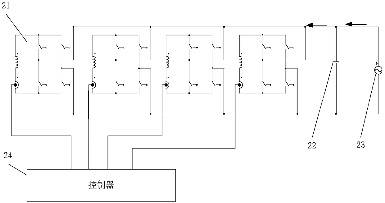
[0029] This embodiment provides a current sharing method for a converter, for example, it can be applied to a converter in a superconducting energy storage system, where the converter includes 2n parallel power sub-modules and capacitors connected in parallel with the power sub-modules , Where n is an integer and n> = 1. figure 2 Shows a schematic diagram of a converter according to an embodiment of the present invention, which includes 4 parallel power sub-modules 21, but figure 2 It is only used as an example, and is not intended to limit the present invention, as long as there are an even number of power sub-modules are feasible. The controller 24 is respectively connected with each power sub-module 21 to send a carrier signal to each power sub-module 21 to equalize the output current of each power sub-module 21. The current source 23 is used to supply power to the converter, and the arrow direction is the current direction. Preferably, a capacitor 22 can also be connected...

Embodiment 2

[0042] This embodiment provides a current-equalizing device for a converter, which can be applied to a converter in a superconducting energy storage system (for example, it can be applied to embodiment 1 figure 2 As shown in the controller 24), the converter includes 2n parallel power sub-modules and capacitors connected in parallel with the power sub-modules, where n is an integer and n> =1, such as image 3 As shown, it includes: a detection module 41, an adjustment module 42, and a control module 4333. Specifically,

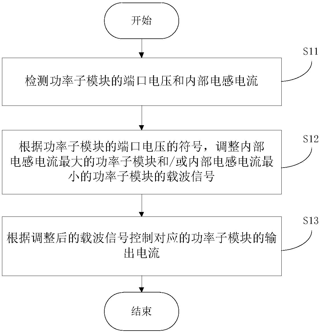
[0043] The detection module 41 is used to detect the port voltage and internal inductance current of the power submodule. For details, please refer to the description of step S11 in Embodiment 1.

[0044] The adjustment module 42 is configured to adjust the carrier signal of the power submodule with the largest internal inductance current and / or the power submodule with the smallest internal inductance current according to the sign of the port voltage of the power s...


PUM


Abstract

The invention provides a current equalizing method and device of a current transformer. The method comprises the following steps of detecting a port voltage and an internal induction current of a power sub-module; adjusting a carrier signal of the power sub-module with maximum internal induction current and / or the power sub-module with minimum internal induction current according to a symbol of the port voltage of the power sub-module; and controlling an output current of the corresponding power sub-module according to the adjusted carrier signal. Therefore, excessive large current and excessive small current are prevented from occurring in the output current of the current transformer, current equalizing of the current transformer is achieved, and the current equalizing effect is improved; and the carrier signal of the power sub-module with maximum / minimum internal induction current is only adjusted each time, and thus, the steps of current equalizing of the current transformer are simplified.

Description

Technical field [0001] The invention relates to the field of power electronic power conversion, in particular to a current equalization method of a converter and a current equalization device of the converter. Background technique [0002] The power electronic converter in the superconducting energy storage system is a device that realizes energy exchange between the superconducting coil and the grid. It is generally connected to the power grid through a transformer, and can independently control the exchange of active and reactive power between the superconducting coil and the power system. Limited by the withstand voltage, switching frequency and power level of power electronic devices, high-power converters mainly use the parallel connection of power sub-modules to achieve power capacity expansion. [0003] Existing parallel converters generally rely on the hardware system to automatically share current. The hardware parameters of each parallel power sub-module of the converter...

Claims


Application Information

Patent Timeline
Patent Type & Authority Patents(China)
IPC IPC(8): H02M5/22
CPCH02M5/22
Inventor 彭傊于弘洋祁欢欢陆振纲宋洁莹蔡林海
Owner GLOBAL ENERGY INTERCONNECTION RES INST CO LTD
Why Eureka
Try Eureka