

Digital pulse width modulator based on IODELAY firmware
A width modulation, digital pulse technology, applied in the field of electronics, can solve the problems such as the basic clock frequency can only reach 1MHz, the design process requirements are high, the structure composition is complex, etc., and the effect of low cost, fine resolution, and simple manufacturing process can be achieved.
- Summary
- Abstract
- Description
- Claims
- Application Information
AI Technical Summary
Problems solved by technology
Method used
Image

Examples
Embodiment Construction
[0023] The present invention will be described in further detail below in conjunction with the accompanying drawings.
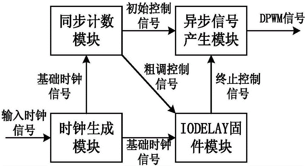
[0024] The present invention provides a high-precision digital pulse width modulator, such as figure 1 As shown, the modulator is composed of a clock generation module, a synchronous counting module, an IODELAY firmware module and an asynchronous signal generation module. The specific circuit diagram of the four modules is as follows: Figure 2 to Figure 5 shown.
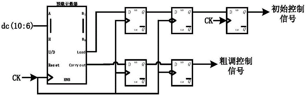
[0025] First, the input 11-bit array DC (10:0) is divided into upper 5-bit DC (10:6) and lower 6-bit DC (5:0).
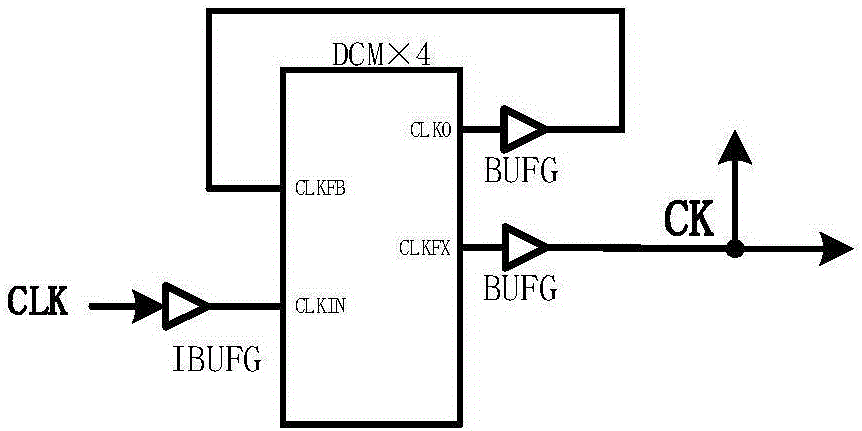
[0026] exist figure 2 In the shown clock generation module, DCM×4 is a 4 times frequency multiplier, and the CLK signal is an input clock signal with a frequency of 50MHz. After the CLK clock signal is spread by the DCM×4 frequency multiplier, the basic clock signal CK with a frequency of 200MHz is obtained, and then the basic clock signal CK is sent to the synchronous counting modu...
PUM
 Abstract
Description
Claims
Application Information