Method and device for determining space isolation band
A space isolation and isolation zone technology, which is applied to electrical components, wireless communication, network planning, etc., can solve the problems of reduced effectiveness of existing setting methods and no setting principles
- Summary
- Abstract
- Description
- Claims
- Application Information
AI Technical Summary
Problems solved by technology
Method used
Image

Examples
Embodiment 1
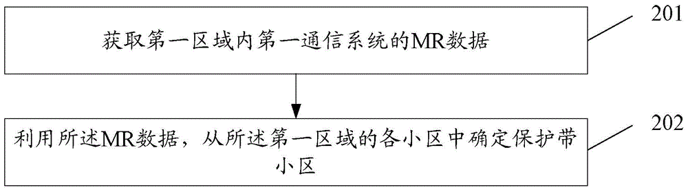
[0099] The method for determining the space isolation zone in this embodiment can be applied in the process of frequency re-cultivation, such as figure 2 shown, including the following steps:
[0100] Step 201: Obtain MR data of the first communication system in the first area; the utilization efficiency of the spectrum resources of the first communication system is lower than the utilization efficiency of the spectrum resources of the second communication system; the first area includes the second an area and a third area; the second area is adjacent to the third area;
[0101] Here, in actual application, the first communication system may be Global System for Mobile Communication (GSM, Global System for Mobile Communication); correspondingly, the second communication system may be Long Term Evolution (LTE, Long Term Evolution) frequency division Duplex (FDD, Frequency Division Duplexing) system or Wideband Code Division Multiple Access (WCDMA, Wideband Code Division Multi...
Embodiment 2
[0159] On the basis of Embodiment 1, this embodiment describes in detail how to determine the space isolation zone.
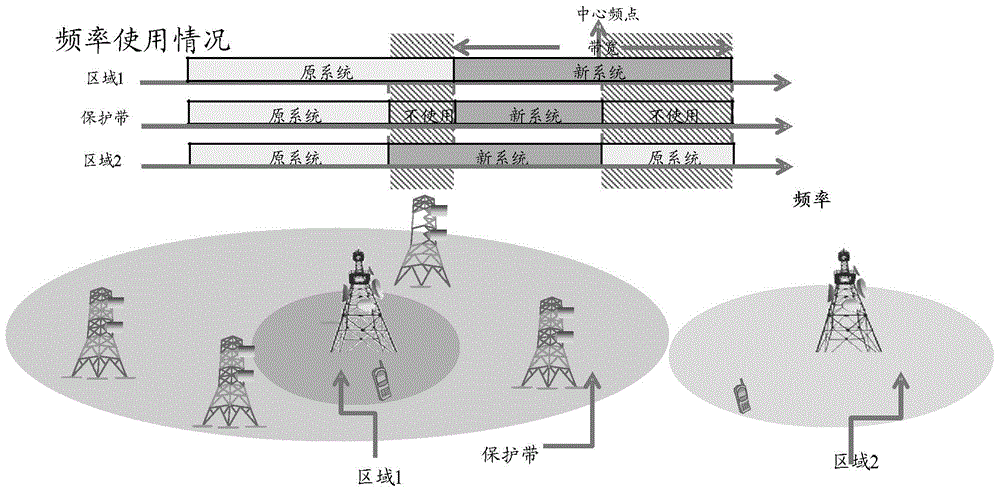
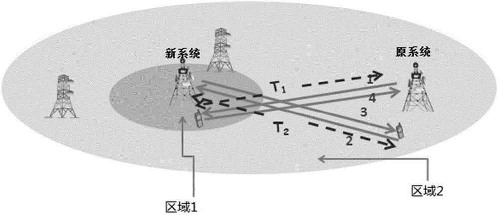
[0160] The application scenario of this embodiment is: Figure 4 As shown, operators need to release part of the spectrum resources used by GSM for the more efficient LTE FDD system. Among them, the rhythm of vacated frequencies between GSM regions (regions 1 and 2) or the frequency bands that can be vacated for LTE FDD systems are inconsistent, so that the LTE FDD center frequency point or bandwidth of frequencies vacated between GSM regions may appear. Inconsistent. Since the base stations and terminal receivers of the GSM and LTE FDD systems have different sensitivities and transmit powers, it is necessary to set guard bands between areas in this scenario to reduce inter-system interference. The frequency of the guard band is used as Figure 5 shown.
[0161] Such as Figure 4 As shown, in an actual scenario, a guard band between the two areas can be se...
Embodiment 3
[0192] The application scenario of this embodiment is: Figure 6 As shown, operators need to vacate part of the frequency spectrum used by GSM for the more efficient WCDMA system to use. Among them, the rhythm of vacated frequencies between the regions of the GSM system (regions 1 and 2) or the frequency bands that can be vacated for the WCDMA system are inconsistent, so that the WCDMA center frequency point or bandwidth of the frequencies vacated between the regions of the GSM system may appear. Inconsistent. Since GSM and WCDMA base stations and terminal receivers have different sensitivities and transmit powers, it is necessary to set guard bands between areas in this scenario to reduce inter-system interference. The frequency of the guard band is used as Figure 7 shown.
[0193] Such as Figure 6 As shown, in an actual scenario, a guard band between the two areas can be set in area 1 or area 2 according to the available frequencies in area 1 and area 2. In this embod...
PUM
 Abstract
Description
Claims
Application Information