

Beverage cup loading machine
A beverage and cup filling technology, which is applied in beverage preparation devices, household appliances, applications, etc., can solve the problems that the person pouring water cannot accurately control the amount of water, cannot place the water cup under the water outlet, and lift the water cup to avoid splashes splash, reduce water splash, reduce water effect
- Summary
- Abstract
- Description
- Claims
- Application Information
AI Technical Summary
Problems solved by technology
Method used
Image

Examples
Embodiment 1
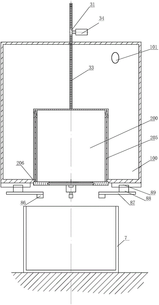
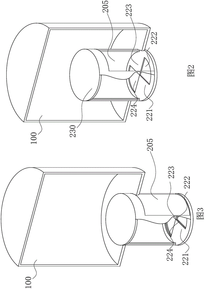
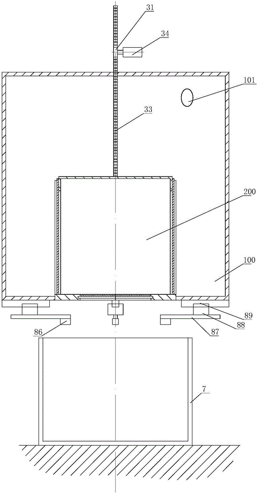
[0045] figure 1 It is a structural schematic diagram of Embodiment 1 of the present invention; figure 2 It is a schematic perspective view of embodiment 1 when the transition container is filled with water from the water injection cavity; image 3 It is a structural schematic diagram when the transition container in embodiment 1 drains outwards; Figure 4 It is a schematic structural diagram of a vertical slide plate used in Embodiment 1 of the present invention; Figure 5 It is a three-dimensional schematic diagram when water enters from the water injection cavity when the embodiment adopts a vertical slide; Image 6 It is a schematic diagram of the structure of the transition container in embodiment 1 when the vertical slide plate is used for draining outwards. figure 2 , 3 , 5, 6 stereograms use partial section drawing for the transition container, and make a partial section section for the left half of the transition container, so as to observe the state of the liqui...
Embodiment 2
[0061] Figure 4 It is a structural schematic diagram of Embodiment 2 of the present invention; Figure 8 It is a schematic diagram of the use state of Embodiment 2 of the present invention. In this state, the touch rod touches the bottom of the cup, so that the movable plate just starts to move upward; Figure 9 It is a schematic diagram of the different state changes of the movable panel in Embodiment 2 of the present invention; Figure 10 It is a schematic diagram of measuring the volume of a water cup by the volume measuring device in Example 2 of the present invention. in, Figure 4 with Figure 8 In , for the wall thickness of pipes, containers, water cups, etc., unless absolutely necessary, they are represented by a single line, but those skilled in the art should be clear that what is represented here is a thick pipe wall, container wall, or cup wall, etc.
[0062] In the figure, the meanings of the reference signs are as follows: 1. Water transfer device; 21. Mova...
Embodiment 3
[0082] Figure 11 It is a structural schematic diagram of Embodiment 3 of the present invention; Figure 12 It is a schematic diagram of the closure plate in Example 3 of the present invention when it is overturned.
[0083] In the figure, the meanings of the reference signs that have appeared in the drawings used in the above embodiments follow the meanings in the drawings of the above embodiments, and the meanings of the newly appearing reference signs are as follows: 24. Overturning motor; 25. Horizontal rotating shaft ; 26, closing plate; 28, lower limit device; 61, multi-cup tray; 62, rotary motor.
[0084] The difference between this embodiment and embodiment 2 is:
[0085] Further preferably, the lower limit device 28 is an infrared distance measuring device. When the lower limit device 28 detects that the distance between the transition container 200 and the bottom of the cup 7 drops to a set distance, it sends a signal to the control device, so that the transition ...
PUM
 Abstract
Description
Claims
Application Information