Electric servo c-type robot welding gun
What is Al technical title?
Al technical title is built by PatSnap Al team. It summarizes the technical point description of the patent document.
A technology of robot welding tongs and electric servo, applied in the direction of resistance welding equipment, electrode characteristics, welding equipment, etc., can solve the problems of short service life of synchronous toothed belt, short service life of welding tongs, low control accuracy, etc., and achieve stable control, The effect of low production cost and small size
Active Publication Date: 2018-06-08
TIANJIN FUZHEN IND EQUIP
View PDF7 Cites 0 Cited by
Summary
Abstract
Description
Claims
Application Information
AI Technical Summary
This helps you quickly interpret patents by identifying the three key elements:
Problems solved by technology
Method used
Benefits of technology
Problems solved by technology
[0004] The current servo welding tongs generally adopt the following two methods: one is the cooperation of the servo motor and the synchronous toothed belt. Since the synchronous toothed belt is prone to jumping teeth during the operation, the control accuracy will not be high during the use of the welding tongs; the synchronous toothed belt Short service life results in short overall service life of welding guns
The other is the servo hollow motor, the only manufacturer of welding tongs, the market is monopolized, and the price of welding tongs is expensive
Method used
Image
Click on the blue label to locate the original text in one second.
Reading with bidirectional positioning of images and text.
Examples
Embodiment Construction
[0018] Below in conjunction with accompanying drawing and preferred embodiment, to the specific implementation mode, structure, feature according to the present invention are described as follows:
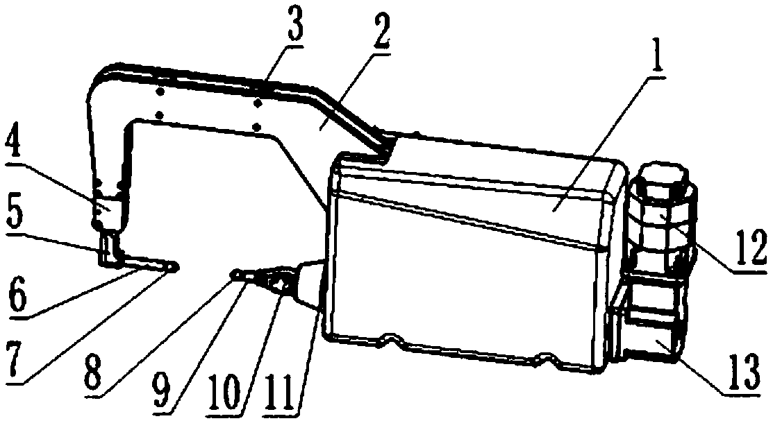
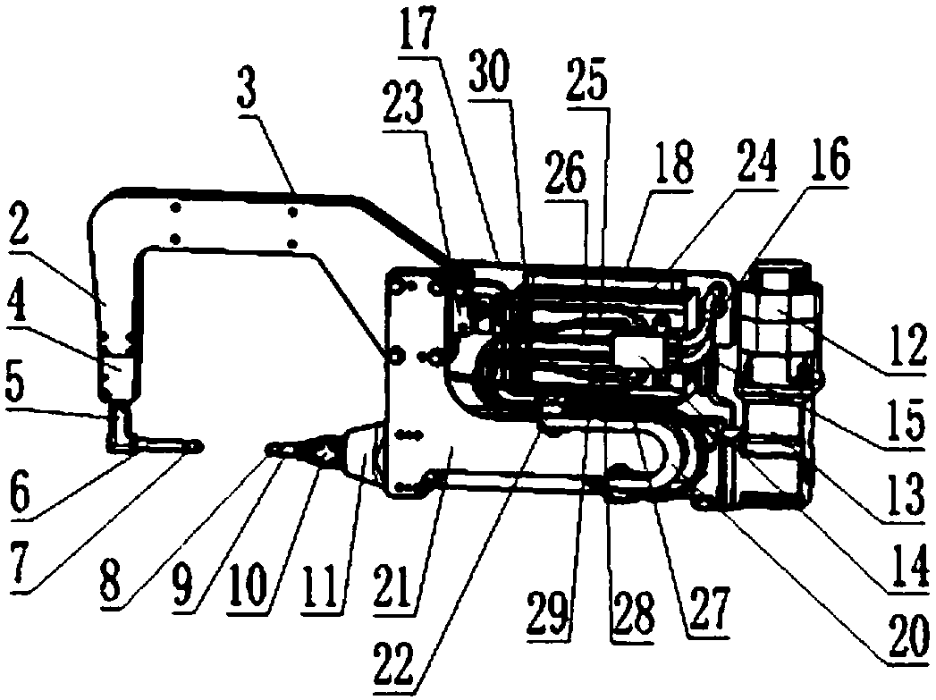
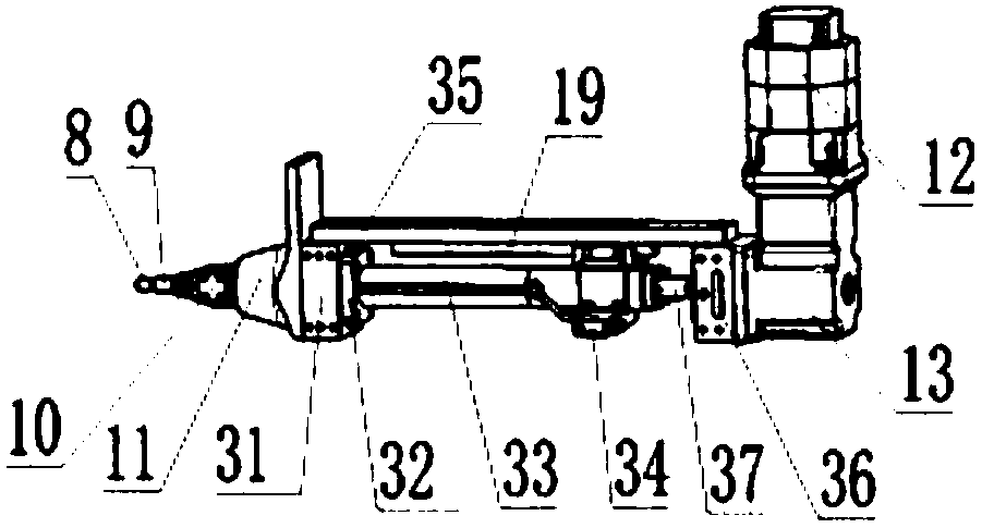
[0019] Such as Figure 1-Figure 3 As shown, an electric servo C-type robot welding tongs includes a drive assembly, a transformer assembly, a base plate 17, a fixed electrode arm assembly, a movable electrode arm assembly, a water pipe assembly, a shield 1 and an upper plate 21.
[0020] The drive assembly includes a servo motor 12 and a reducer 13 ; the servo motor 12 is connected to the reducer 13 , and the reducer 13 is connected to a ball screw 37 .
[0021] The transformer assembly includes a transformer 18, a copper bar 22, a copper bar 23, a copper bar 34 and a soft copper bar 20. The transformer 18 is installed on the substrate 17, and the copper bar 22, the copper bar 23 and the transformer 18 To connect, one end of soft copper bar 20 is connected with copper bar one 22, ...
PUM
Abstract
The invention relates to an electric servo C-shaped robot welding clamp. The electric servo C-shaped robot welding clamp comprises a driving module, a protective cover, a substrate, an upper plate, a fixed electrode arm module, a movable electrode arm module, a water pipe module and a transformer module. The driving module includes a servo motor and a speed reducer; the fixed electrode arm module includes a welding clamp arm connecting bracket, an aluminum alloy welding clamp arm, a copper connecting block, a copper welding clamp arm, a fixed electrode rod and a fixed electrode cap; and the movable electrode arm module includes a movable electrode arm, a movable electrode rod, a movable electrode arm cover, a movable electrode cap, a linear guide rail, a plummer linear bearing, a ball screw and a push rod. The water pipe module includes a distributor, a water inlet pipe, a water return pipe, a fixed electrode arm water return pipe, a movable electrode arm water return pipe, a transformer water return pipe, a fixed electrode arm water inlet pipe, a transformer water inlet pipe, a movable electrode arm water inlet pipe and a water pipe mounting bracket; and the transformer module includes a transformer, a copper bar 1, a copper bar 2, a copper bar 3 and a soft copper bar. The electric servo C-shaped robot welding clamp adopts a modular servo technology, and is precise in control.
Description
technical field [0001] The invention relates to a robot welding device, in particular to an electric servo C-type robot welding tongs. Background technique [0002] At present, welding is a common processing technology in the automobile manufacturing industry. As one of them, spot welding is widely used in the automobile manufacturing industry. By clamping two pieces of metal, a large current is passed through a small contact surface instantly, melting and fusing the two pieces of metal, and the effect of solid connection is achieved after cooling. The spot welding process will not damage the internal structure of the workpiece, and there is no need to add other welding materials. Due to the different welding positions and postures, the requirements for welding tongs are also different, and they are generally divided into C-type welding tongs and X-type welding tongs. [0003] In recent years, the domestic automobile industry has developed rapidly, the degree of automation...
Claims
Application Information
Patent Timeline
Application Date:The date an application was filed.
Publication Date:The date a patent or application was officially published.
First Publication Date:The earliest publication date of a patent with the same application number.
Issue Date:Publication date of the patent grant document.
PCT Entry Date:The Entry date of PCT National Phase.
Estimated Expiry Date:The statutory expiry date of a patent right according to the Patent Law, and it is the longest term of protection that the patent right can achieve without the termination of the patent right due to other reasons(Term extension factor has been taken into account ).
Invalid Date:Actual expiry date is based on effective date or publication date of legal transaction data of invalid patent.