

Multifunctional hydraulic combined punching and shearing machine and punching and shearing method thereof
A punching and shearing machine, multi-functional technology, applied in the direction of shearing device, shearing machine equipment, other manufacturing equipment/tools, etc., can solve problems such as good economic benefits, and achieve the effects of convenient use, cost reduction, and deformation avoidance
- Summary
- Abstract
- Description
- Claims
- Application Information
AI Technical Summary
Problems solved by technology
Method used
Image

Examples
Embodiment 1
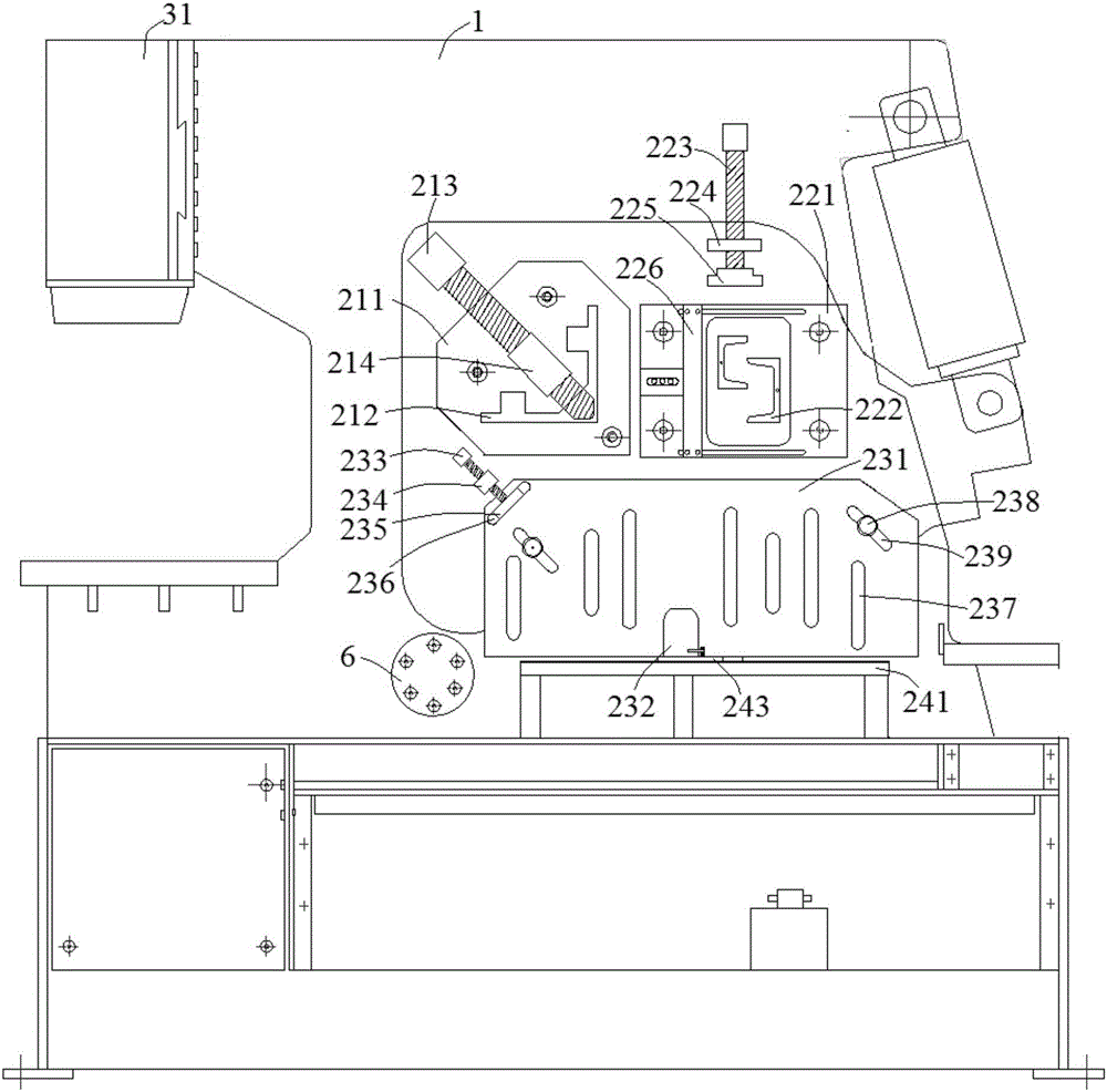
[0070] combine figure 1 , a multifunctional hydraulic combined punching and shearing machine of the present embodiment, which is provided with a pressing mechanism on the front of the punching and shearing machine body 1, and the pressing mechanism includes a pressing assembly of 3 stations; wherein:
[0071] The first pressing assembly includes a first material limiting plate 211, a first pressing screw 213 and a first fixing sleeve 214, the first material limiting plate 211 is fixed on the fuselage 1 by bolts, and the first material limiting plate 211 is provided with a There is a first feeding chute 212, and the first feeding chute 212 is an irregular "L"-shaped structure. The first compression screw 213 is arranged on the first material limiting plate 211 through the first fixing sleeve 214 , and the first compression screw 213 can move toward the top angle direction of the first feeding groove 212 . The first pressing assembly of this embodiment is mainly suitable for sh...
Embodiment 2
[0079] to combine Figure 5 , Figure 6 and Figure 7 , a multifunctional hydraulic combined punching and shearing machine in this embodiment includes an oil cylinder fixing mechanism. In this embodiment, a "T-shaped" side plate groove 321 is set on the oil cylinder side plate 32 of the hydraulic cylinder 31, and a "T-shaped" side plate boss 111 is correspondingly set on the fuselage side plate 11 of the fuselage 1, and in the machine A first side plate fixing hole 112 is provided on both sides of the body side plate 11 in the length direction, and a second side plate fixing hole 322 is provided on both sides of the cylinder side plate 32 in the length direction.
[0080] When assembling the punching and shearing machine, insert the "T-shaped" side plate boss 111 on the side of the fuselage 1 into the "T-shaped" side plate groove 321 on the side of the hydraulic cylinder 31, and then use the second fastening bolt 33 to pass through the first The side plate fixing hole 112 a...
Embodiment 3
[0082] to combine Figure 8 , Figure 9 and Figure 10 , a multifunctional hydraulic combined punching and shearing machine in this embodiment is an oil cylinder fixing mechanism of another structural design. In this embodiment, a dovetail-shaped boss is provided on the cylinder side plate 32 of the hydraulic cylinder 31 , and correspondingly, a dovetail-shaped groove is provided on the fuselage side plate 11 of the fuselage 1 .
[0083] When assembling the punching and shearing machine, insert the dovetail-shaped boss on the side of the hydraulic cylinder 31 into the dovetail-shaped groove on the side of the fuselage, and then use the second fastening bolt 33 to pass through the fixing hole 112 of the first side plate and the second side plate. The plate fixing hole 322 securely connects the hydraulic cylinder 31 and the fuselage 1 . Since the contact surface between the hydraulic cylinder 31 and the fuselage 1 is a matching dovetail surface, it is more convenient and fast...
PUM
 Abstract
Description
Claims
Application Information