Machine tool

A machine and workpiece technology, applied in the field of processing machines, can solve problems such as difficult rotation connections, complex maintenance of energy lines, etc., and achieve the effect of all-round processing

Inactive Publication Date: 2016-12-14
GROB WERKE & K G
View PDF7 Cites 0 Cited by
  • Summary
  • Abstract
  • Description
  • Claims
  • Application Information

AI Technical Summary

Problems solved by technology

[0003] It is known in the prior art that this energy is introduced into the workpiece table via an energy line. The energy supply is solved by permanently fixed connections. This energy line must be constructed such that in principle it is possible to surround the above-mentioned The axis of rotation implements a rotational movement. These boundary conditions accordingly lead to complex and difficult-to-maintain rotational connections for the energy lines.

Method used


Image

  • Machine tool
  • Machine tool
  • Machine tool

Examples


Embodiment Construction

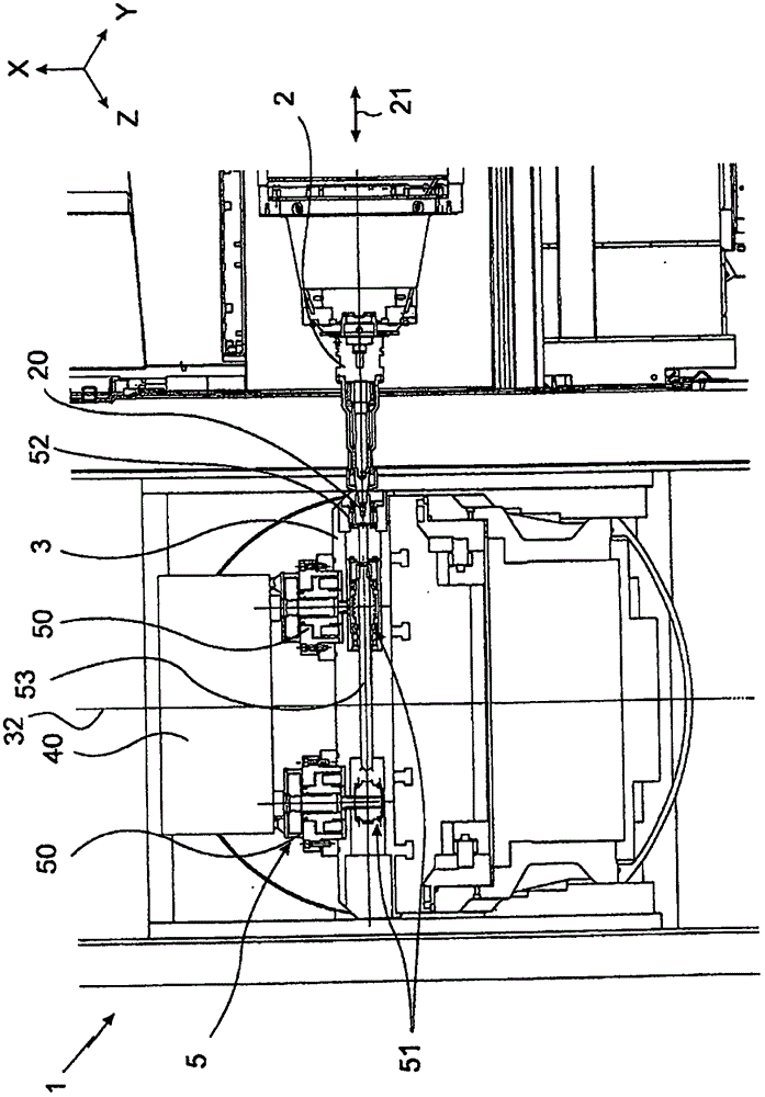
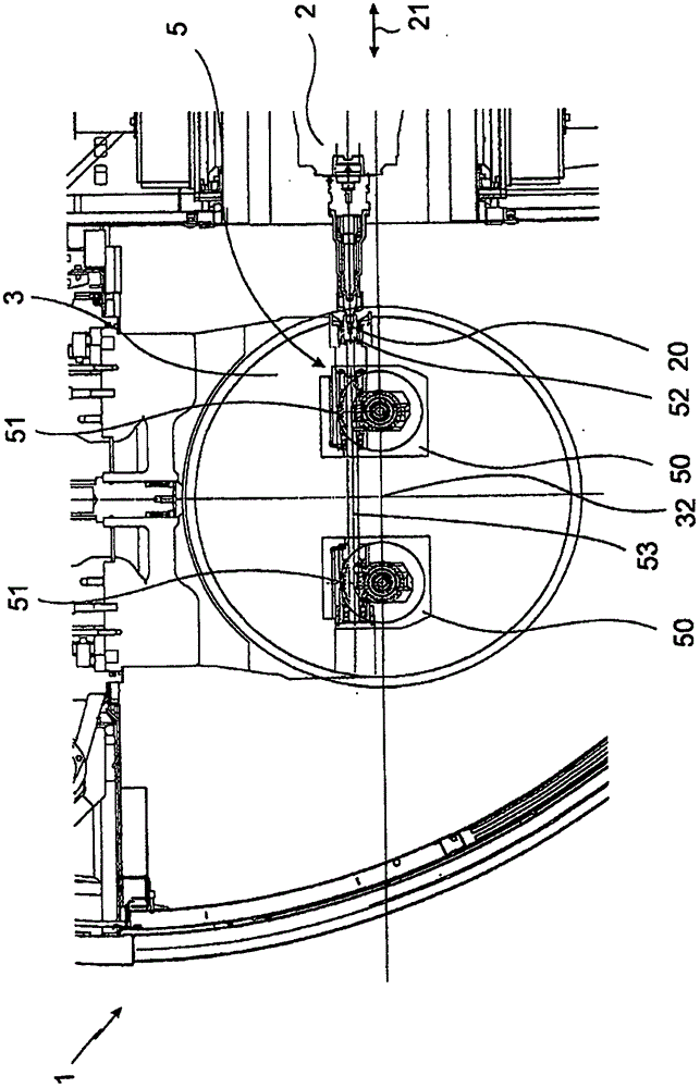
[0053] figure 1 A side view of a processing machine 1 according to a first embodiment is shown. The processing machine 1 is designed to process workpieces, not shown, which are held by a pallet 40. Below the pallet 40 there will be The manner further illustrated is held on a workpiece table 3 . The workpiece table 3 is rotatable about a vertical axis 32 so that the pallet 40 is correspondingly rotatable.

[0054] For machining the workpiece, there is a motor spindle 2 which is designed to receive a tool and drive it rotatably. This can be, for example, a drill or a grinding head. However, the The motor spindle 2 can also accommodate a tool which is designed specifically for actuating the device on the workpiece table 3 in a manner which will be explained further below. For this purpose, for example, a hexagonal head can be accommodated.

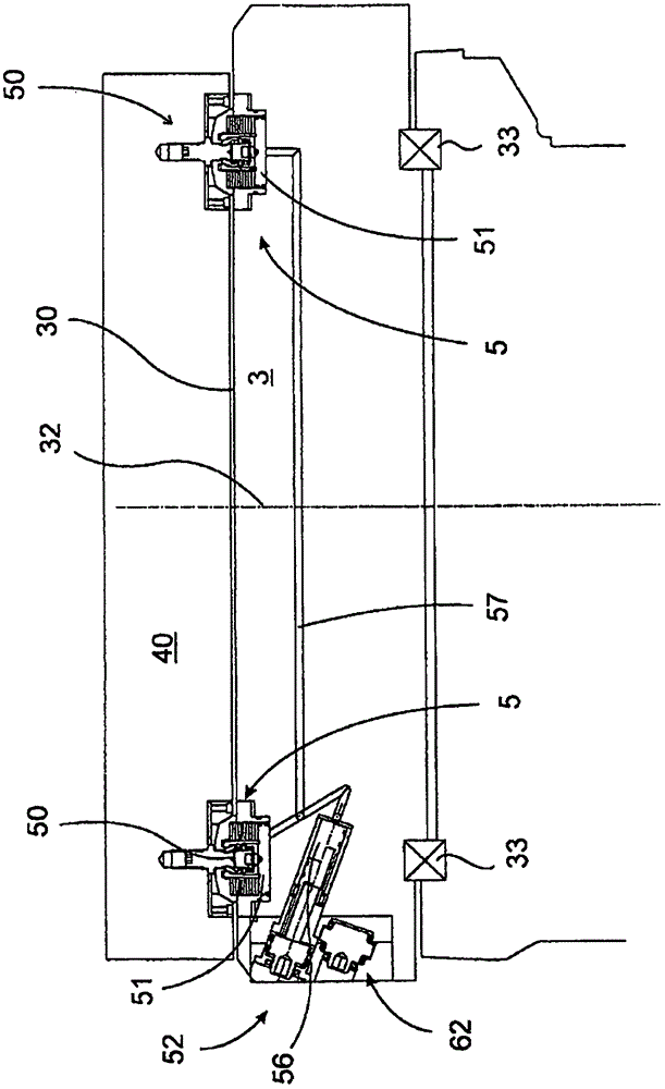
[0055] A clamping device 5 is arranged in the workpiece table 3. The clamping device 5 has two clamping mechanisms 50. The clamping mechani...


PUM


Abstract

The invention refers to a machine tool with a work piece table, wherein a clamping or lifting means disposed on the work piece table is driven by temporary power transmission from outside the work piece table. The invention also refers to a corresponding method.

Description

technical field [0001] The invention relates to a machining machine, in particular a cutting machining machine, having at least one motor spindle for rotatably driving each tool and a workpiece table, the at least one workpiece being supported directly or indirectly by means of the workpiece The pallet is clamped on the workpiece table by the clamping device during the cutting process. In order for the workpiece or the pallet supporting the workpiece to be transferred from the front field to the workpiece table and back, a roller guide can be provided at least on the surface of the workpiece table, and the workpiece or the pallet Placed on the roller guide rail for transport. The pallet can be equipped with guide wheels on its underside, wherein the guide wheels hold the workpiece or the pallet on the workpiece table In the positioning, they are respectively located in a guide rail section. A lifting device can be arranged on the workpiece table. Background technique [00...

Claims


Application Information

Patent Timeline
Patent Type & Authority Applications(China)
IPC IPC(8): B23Q5/54B23Q1/00B23Q1/26B23Q3/06B23Q3/08B23Q37/00
CPCB23Q1/0009B23Q1/26B23Q3/06B23Q3/082B23Q5/54B23Q37/00B23Q2230/002B23Q1/25B23Q7/14B23Q11/00B23Q2703/02B23Q2701/02B23C1/04B23Q1/52B23Q5/04
Inventor B·格鲁博
Owner GROB WERKE & K G
Why Eureka
Try Eureka