Tunneling machine and tunneling method

A technology of roadheader and propulsion system, which is applied in earthwork drilling, mining equipment, tunnels, etc. It can solve problems such as delay in construction period and stoppage of jammed shields, and achieve the effects of preventing torsion, increasing compressive strength, and increasing engineering safety

Active Publication Date: 2016-12-14
CHINA RAILWAY ENGINEERING EQUIPMENT GROUP CO LTD
View PDF6 Cites 7 Cited by
  • Summary
  • Abstract
  • Description
  • Claims
  • Application Information

AI Technical Summary

Problems solved by technology

[0004] The technical problem mainly solved by the present invention is that the present invention provides a roadheader used in tunnel excavation. The roadheader of the present invention has high excavation efficiency, energy saving and environmental protection, and at the same time effectively solves the problem in the prior art that the construction period is delayed due to shield jamming , the present invention also provides a tunneling method to solve the problem of jammed shield stoppage and delay of construction period due to large buried depth and broken bad geology

Method used


Image

  • Tunneling machine and tunneling method
  • Tunneling machine and tunneling method
  • Tunneling machine and tunneling method

Examples


Embodiment Construction

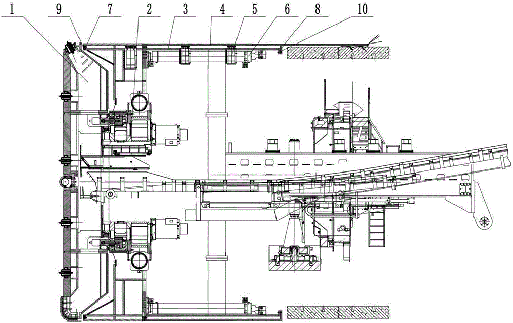
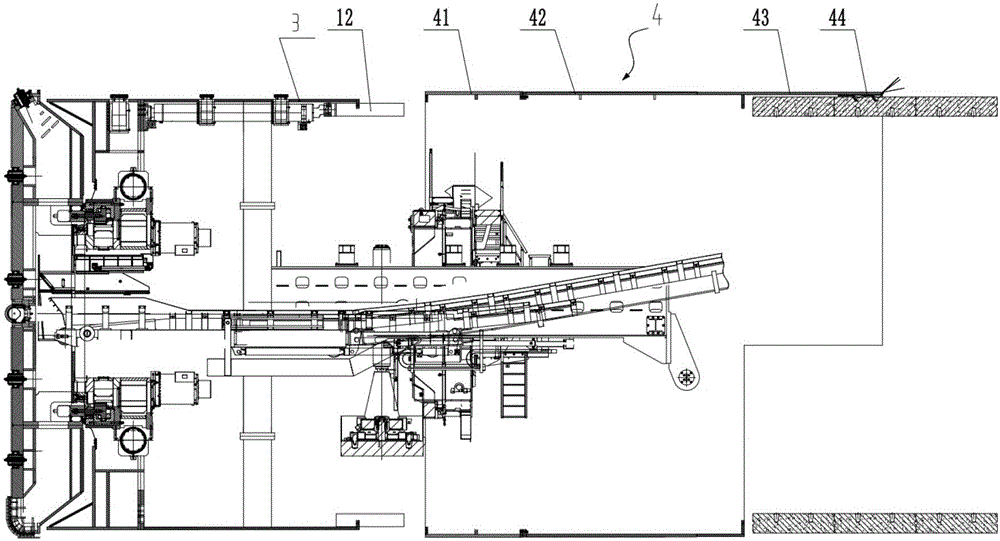
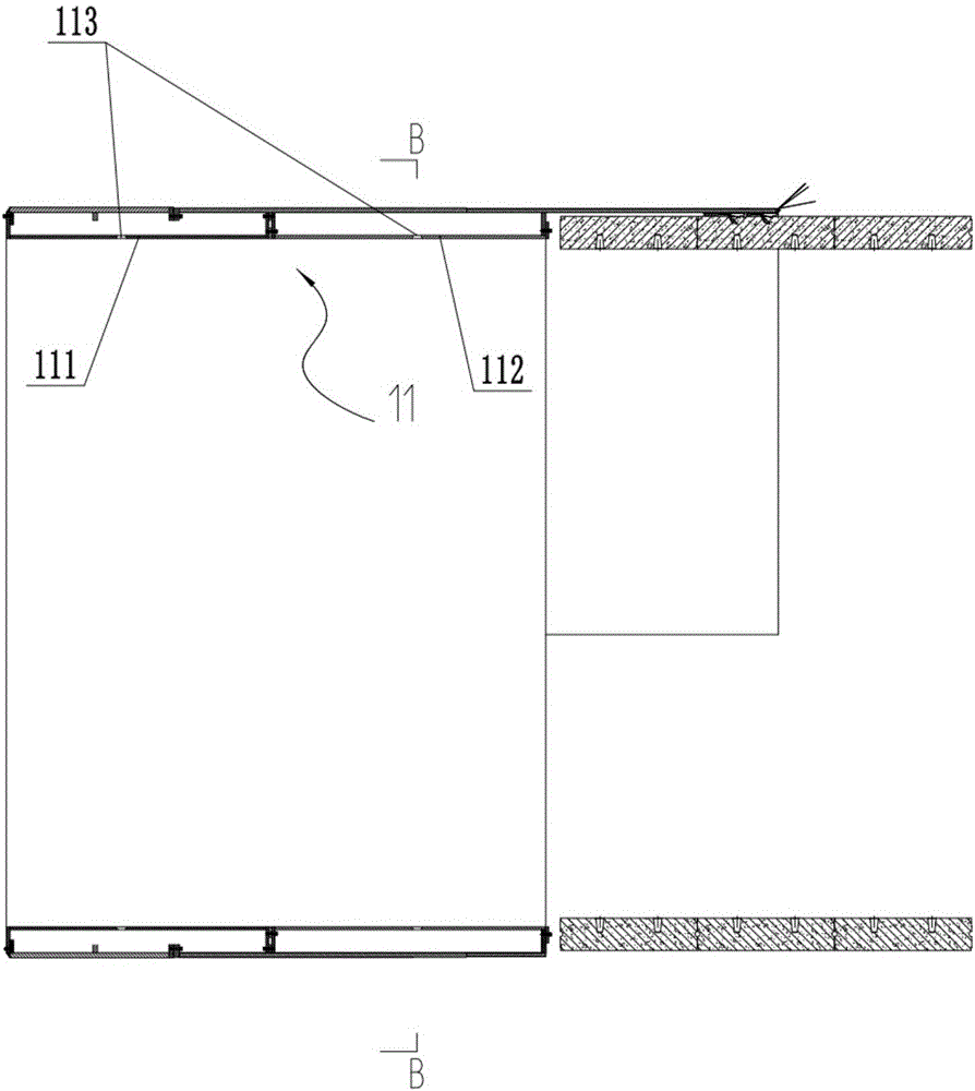
[0040] In order to facilitate the understanding of the present invention, the present invention will be described in more detail below in conjunction with the accompanying drawings and specific embodiments. Preferred embodiments of the invention are shown in the accompanying drawings. However, the present invention can be implemented in many different forms and is not limited to the embodiments described in this specification. On the contrary, these embodiments are provided to make the understanding of the disclosure of the present invention more thorough and comprehensive.

[0041] It should be noted that, unless otherwise defined, all technical and scientific terms used in this specification have the same meaning as commonly understood by those skilled in the technical field of the present invention. Terms used in the description of the present invention are only for the purpose of describing specific embodiments, and are not used to limit the present invention. The term "...


PUM


Abstract

The invention discloses a tunneling machine. The tunneling machine comprises a cutterhead, a driving set for driving the cutterhead to rotate, a shield, an adjusting oil cylinder and a propelling system, wherein the shield comprises an inner shield connected onto the rear end of the cutterhead and an outer shield which sleeves the outer side of the inner shield and is fixedly connected with the inner shield; a fit clearance is formed between the inner shield and the outer shield; the adjusting oil cylinder is fixedly arranged on the inner shield; a retractable piston of the adjusting oil cylinder penetrates through the fit clearance between the inner shield and the outer shield; and the propelling system is fixedly connected into an inner cavity of the inner shield and is used for propelling the tunneling machine. Meanwhile, the invention further provides a tunneling method, aiming at solving the problems of getting stuck and stopping, caused by great-depth and crushed tunnels in unfavorable geological conditions. The tunneling machine provided by the invention has the advantages of high tunneling efficiency, energy saving, environment protection and the like.

Description

technical field [0001] The invention relates to the technical field of tunnel construction, in particular to a tunneling machine and a tunneling method in the tunneling engineering of poor-quality geology. Background technique [0002] At present, the construction of large-diameter tunnels at home and abroad often adopts full-face hard rock tunnel boring machine (TBM) construction. The roadheader in the prior art includes a cutterhead, a drive system for driving the cutterhead to rotate, a propulsion system for advancing the roadheader supported by segments, and a shield structure for supporting, etc. The construction of tunnel boring machine with shield structure has the characteristics of safety, efficiency and reliability. However, when the roadheader encounters unfavorable geological conditions such as large burial depth and fragmentation, the surrounding rock shrinks and deforms greatly, and it is easy to collapse, which makes the shield body of the roadheader very pro...

Claims


Application Information

Patent Timeline
Patent Type & Authority Applications(China)
IPC IPC(8): E21D9/08
Inventor 翟国强贺飞卓兴建陈金波
Owner CHINA RAILWAY ENGINEERING EQUIPMENT GROUP CO LTD
Why Eureka
Try Eureka