Recyclable cylindrical fiber glass gas blaster and manufacturing method thereof

A glass fiber, cylindrical technology, used in chemical instruments and methods, blasting cylinders, glass/slag layered products, etc., can solve problems such as high failure rate, difficult maintenance, air leakage, etc.

Inactive Publication Date: 2016-12-14
郭远军
View PDF1 Cites 0 Cited by
  • Summary
  • Abstract
  • Description
  • Claims
  • Application Information

AI Technical Summary

Problems solved by technology

[0011] The object to be realized by the present invention is: to reduce the weight of the existing gas blaster, reduce the production cost, and compare with the prior art, the storage energy of the steel cylinder with the same size is larger, simplify the inflation process, and overcome the sealing problem; to solve the above-mentioned background technology Existing in the existing gas blasters: 1. The thickness of the blasting cylinder is 8-60mm, and the density of the steel is high, and the gas blasters generally have the problems of heavy w

Method used


Image

  • Recyclable cylindrical fiber glass gas blaster and manufacturing method thereof
  • Recyclable cylindrical fiber glass gas blaster and manufacturing method thereof
  • Recyclable cylindrical fiber glass gas blaster and manufacturing method thereof

Examples


Embodiment 1

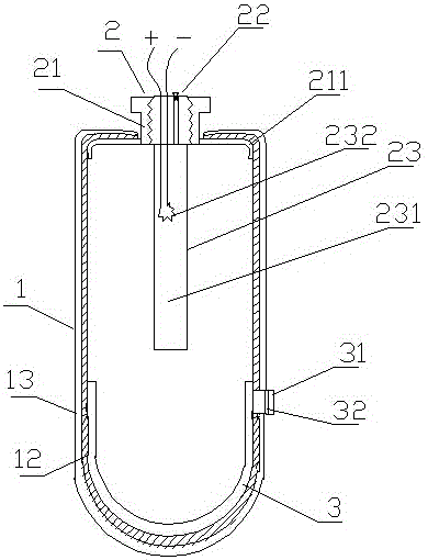
[0097] Example 1 as figure 1 As shown, a reusable cylindrical fiberglass gas blaster includes an energy storage device 1 and an inflatable detonation device 2, the energy storage device 1 is equipped with an inflatable detonation device 2 at one end, and the other end is sealed or integrally formed; The energy device 1 is made of solidified glass fiber material. The energy storage device 1 is cylindrical; Window 31, the energy-dissipating window 31 is sealed and installed with a constant-pressure burst disc 32, and the energy-dissipating inner cover 3 is made of metal.

[0098] As a further specific description of the above implementation, the energy storage device 1 has a two-layer structure, and the energy storage device 1 includes a mesh layer 12 and a hardened layer 13 distributed from the inside to the outside.

[0099] As a further specific description of the above implementation, the inflatable detonating device 2 includes a sealing base 21 , and an inflating mechanism...

Embodiment 2

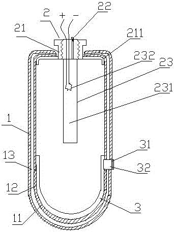
[0113] Embodiment two: the difference with embodiment one is: (such as figure 2 As shown) the energy storage device (1) has a three-layer structure, which consists of a base layer (11), a mesh layer (12) and a hardened layer (13) from inside to outside; the mesh layer (12) is glass Fiber material, the hardened layer (13) is made of epoxy resin glue material, and the base layer (11) is made of polyethylene material.

Embodiment 3

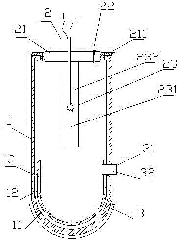
[0114] Embodiment three: the difference with embodiment two is: (such as image 3 As shown), the threaded structure in the middle of the sealing base 21 is inwardly recessed; this structure is convenient for transportation and saves the overall volume, and at the same time, it is convenient for protecting the inflatable detonator 2 from being hit.


PUM

PropertyMeasurementUnit
Thicknessaaaaaaaaaa
Thicknessaaaaaaaaaa
Tensile strengthaaaaaaaaaa

Abstract

The invention discloses a recyclable cylindrical fiber glass gas blaster and a manufacturing method thereof. The recyclable cylindrical fiber glass gas blaster comprises an energy storing device and an inflating and blasting device, wherein the blasting device is installed at one end of the energy storing device, the other end of the energy storing device is sealed or integrally formed, and the energy storing device is formed by curing glass fibers and is cylindrical; and an inner energy releasing cover is arranged on the inner layer of the bottom of the energy storing device and is provided with an energy releasing window, the energy releasing window is provided with a fixed-pressure blasting sheet, and the inner energy releasing cover is made of metal. The recyclable cylindrical fiber glass gas blaster has the advantages that the thickness is small, the weight is light, transportation and installation are convenient, manufacturing is simple, the consumable cost is low, the production cost is low, inflation is fast, the sealing performance is good, and the service life is long.

Description

technical field [0001] The invention belongs to the blasting field and relates to a blasting device, in particular to a reusable cylindrical glass fiber gas blaster and a manufacturing method thereof. Background technique [0002] Gas blasting technology is the use of gasification and expansion of liquid or solid substances that are easy to gasify to generate high-pressure gas, so that the surrounding medium expands to do work and cause fragmentation; gas blasting technology is widely used in mining, geological exploration, cement, steel, electric power, etc. Industry, subway and tunnel and municipal engineering, underwater engineering, and emergency rescue. At present, the equipment used in gas blasting technology is a gas blasting tube. The blasting tube mainly includes an inflatable structure, a detonating structure, an expansion medium storage structure and a sealing structure. It has the following disadvantages: [0003] At present, the expansion medium storage structu...

Claims


Application Information

Patent Timeline
IPC IPC(8): F42B3/04F42B3/06F42B3/28F42B33/00E21C37/14E21D9/00B32B1/02B32B27/30B32B27/36B32B27/34B32B27/32B32B27/02B32B27/12B32B17/02B32B17/12B32B9/00B32B9/04B32B15/14B32B33/00
CPCF42B3/045B32B1/02B32B5/02B32B5/26B32B9/00B32B9/047B32B15/14B32B27/308B32B27/32B32B27/36B32B33/00B32B2255/02B32B2262/0261B32B2262/0276B32B2262/101B32B2262/106B32B2307/51B32B2307/54E21C37/14E21D9/006F42B3/06F42B3/28F42B33/00
Inventor 郭远军
Owner 郭远军
Why Eureka
Try Eureka