
Open temperature sensor and preparation method thereof

A temperature sensor, an open technology, applied to thermometers, thermometers with directly heat-sensitive electric/magnetic elements, instruments, etc., can solve problems such as product reliability, wire sheath damage, and slow response time. Achieve high reliability, avoid oxidation and corrosion damage, and reduce heat capacity

Inactive Publication Date: 2016-12-14
肇庆爱晟传感器技术有限公司
View PDF6 Cites 11 Cited by
  • Summary
  • Abstract
  • Description
  • Claims
  • Application Information

AI Technical Summary

Problems solved by technology

The shortcomings of the existing technology are: first, the thermal expansion coefficients of the three materials, epoxy resin, metal shell, and wire, are all different, resulting in the force of expansion or contraction between the materials when the temperature sensor is working with drastic changes in the ambient temperature. Mutual destructive effect, the specific performance is that the expansion coefficient of epoxy resin is the smallest, the expansion coefficient of the wire is 2-10 times larger than that of the metal shell, and the volume is much larger than that of the metal shell. In a high temperature environment, the wire will expand to the metal shell In addition to the expandable volume, it will cause a strong drag force between the wire and the epoxy resin in the process of expanding to the space outside the metal shell, which will cause the wire sheath to be damaged and the epoxy resin to peel off, thus causing hidden dangers in product reliability ;Secondly, the heat capacity of the thermistor at the head of the temperature sensor increases after being packaged twice, resulting in a slower response time

Method used


Image

  • Open temperature sensor and preparation method thereof
  • Open temperature sensor and preparation method thereof
  • Open temperature sensor and preparation method thereof

Examples


Embodiment Construction

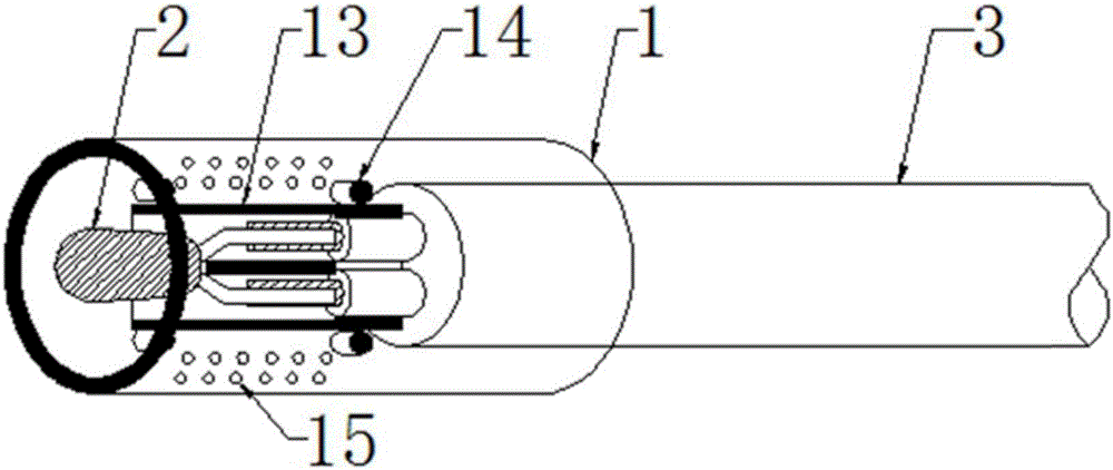
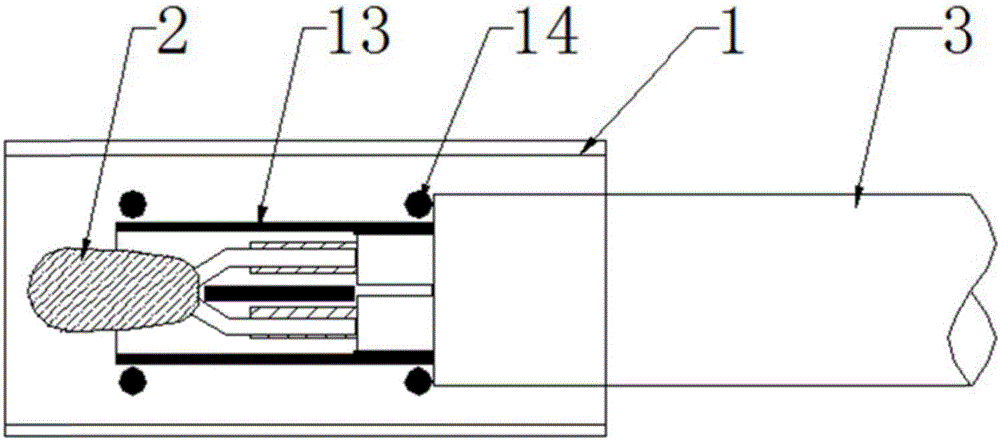
[0025] Please also see figure 1 with figure 2 , which are respectively a structural schematic diagram and a top view of the open temperature sensor of the present invention. The open temperature sensor includes a housing 1 , a thermistor 2 and a wire 3 . The thermistor 2 is connected to the wire 3 by welding. The casing 1 is sleeved on the outside of the thermistor 2 , and one end of the shell is sleeved on the end of the wire 3 .

[0026] The housing 1 includes two symmetrical semi-cylindrical hollow housings 11 and 12, and the semi-cylindrical hollow housings 11 and 12 are correspondingly provided with snap-fit ​​insulating partitions 13 and matching butt joint posts. 14. Two symmetrical semi-cylindrical hollow shells 11 and 12 are buckled correspondingly to form a cylindrical shell 1 , and the butt joint posts 14 are correspondingly fastened so that the insulating partition 13 is sleeved outside the solder joints of the thermistor 2 and the wire 3 . In this embodiment...


PUM


Abstract

The invention discloses an open temperature sensor and a preparation method thereof. The open temperature sensor comprises a shell, a thermistor, and a wire. The thermistor and the wire are connected by means of welding. The shell sleeves the thermistor, and one end of the shell sleeves the end of the wire. Insulating partitions are arranged inside the shell, and the insulating partitions sleeve the solder joint of the thermistor and the wire. Compared with the prior art, the preparation method of the open temperature sensor of the invention is simple to operate and highly operable, greatly improves the production efficiency, and reduces the labor cost. In addition, the solder joint of the open temperature sensor is of high reliability in a cold and hot shock environment, and is prevented from being oxidized and corroded in an open environment. The shell is fixed by abutting clamp columns, the solder joint is insulated and protected by the insulating partitions, the shell is prevented from being filled with excessive resin, so that the heat capacity is reduced, and the thermal response time is shortened greatly.

Description

technical field [0001] The invention belongs to the field of electronic components, in particular to an open temperature sensor and a preparation method thereof. Background technique [0002] Current temperature sensor probes generally include thermal metal shells, thermistors, encapsulating materials, potting materials and wires. In the existing technology, the thermistor is welded to the wire, encapsulated with epoxy resin, then inserted into a metal shell, and finally filled with epoxy resin to complete the package. The shortcomings of the existing technology are: first, the thermal expansion coefficients of the three materials, epoxy resin, metal shell, and wire, are all different, resulting in the force of expansion or contraction between the materials when the temperature sensor is working with drastic changes in the ambient temperature. Mutual destructive effect, the specific performance is that the expansion coefficient of epoxy resin is the smallest, the expansion ...

Claims


Application Information

Patent Timeline
IPC IPC(8): G01K7/22
CPCG01K7/22
Inventor 黄俊维段兆祥杨俊唐黎民
Owner 肇庆爱晟传感器技术有限公司
Learn More