PWM self-testing method

A self-detection, square wave signal technology, applied in the direction of measuring electricity, measuring devices, measuring electrical variables, etc., can solve the problems of low filter cut-off frequency, complex processing circuit, and large volume, so as to improve real-time performance and reduce complexity And volume, improve the effect of product quality

Active Publication Date: 2016-12-14
中国航发控制系统研究所
View PDF9 Cites 5 Cited by
  • Summary
  • Abstract
  • Description
  • Claims
  • Application Information

AI Technical Summary

Problems solved by technology

However, the PWM signal received by the actuator is not necessarily the output value of the controller, such as a virtual connection of the plug, etc., causing the actuator to perform unexpected actions, which is dangerous for some control systems with high reliability and safety requirements. Therefore, it is necessary to detect in real time whether the PWM signal received by the actuator meets expectations, and if it does not meet expectations, fault handling should be performed, such as control channel switching
[0003] At present, the self-detection of PWM output signals usually uses hardware filtering and then AD to collect DC signals for processing. The processing circuit is relatively complex and the volume is relatively large, and because the cut-off frequency of the filter is relatively low, the real-time performance is poor and the delay is average. Above 500ms, it is difficult to meet the requirements of the control system with high security and high precision (such as speed fluctuation less than 0.1%)

Method used


Image

  • PWM self-testing method

Examples


Embodiment Construction

[0015] The present invention will be further described below in conjunction with specific drawings and embodiments.

[0016] In order to effectively improve the real-time performance of PWM detection, reduce the complexity and volume of hardware circuits, and improve the accuracy of PWM detection, the self-test method of the present invention includes the following steps:

[0017] Step 1, collecting the output PWM current signal, and converting the PWM current signal into a square wave signal;

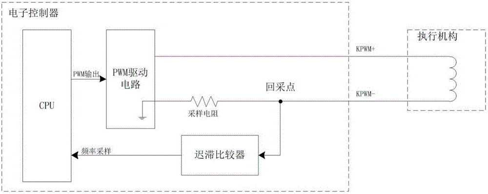
[0018] Specifically, in order to improve the anti-interference ability, the sampling point for collecting the PWM current signal is set in the electronic controller that outputs the PWM current signal, and the PWM current signal is converted into a square wave signal by a hysteresis comparator.

[0019] Generally, the electronic controller includes a CPU for generating PWM signals and a PWM drive circuit, and the PWM drive circuit is connected to the actuator, such as figure 1 shown. ...


PUM


Abstract

The invention relates to a PWM self-testing method. The method comprises: step one, collecting an outputted PWM current signal and converting the PWM current signal into a square wave signal; step two, collecting a duty ratio of the square wave signal to obtain a PWM output signal recovery value PWMWA and comparing the PWMWA with a PWM output signal front period value PWMPV to obtain a collection comparison difference; and step three, comparing the collection comparison difference with a preset threshold value and outputting a PWM self-testing result based on a comparison result. According to the invention, the real-time performance of PWM detection can be improved effectively; the complexity degree and size of the hardware circuit can be reduced; the PWM detection precision can be enhanced; the application range is wide; and the security and reliability are high.

Description

technical field [0001] The invention relates to a method, in particular to a PWM self-detection method, which belongs to the technical field of PWM detection in digital electronic control. Background technique [0002] PWM signal is a commonly used control signal in industrial control. It is mainly used to control various actuators and is a key control signal. However, the PWM signal received by the actuator is not necessarily the output value of the controller, such as a virtual connection of the plug, etc., causing the actuator to perform unexpected actions, which is dangerous for some control systems with high reliability and safety requirements. Therefore, it is necessary to detect in real time whether the PWM signal received by the actuator meets expectations, and if it does not meet expectations, fault handling should be performed, such as control channel switching. [0003] At present, the self-detection of PWM output signals usually uses hardware filtering and then ...

Claims


Application Information

Patent Timeline
Patent Type & Authority Applications(China)
IPC IPC(8): G01R29/027G01R31/02
CPCG01R29/0273G01R31/50
Inventor 邵腾飞张学军徐凯健李伟张星星
Owner 中国航发控制系统研究所
Why Eureka
Try Eureka