Vibration diaphragm and miniature sounder with the vibration diaphragm

A film layer and vibration system technology, applied in the direction of planar diaphragm, sensor, loudspeaker, etc., can solve problems such as cracking, shortening the service life of micro-speakers, and reducing the reliability of micro-speakers, so as to achieve long service life and improve Reliability and stability, enhanced stretch and elastic effects

Inactive Publication Date: 2016-12-14
GOERTEK INC
View PDF6 Cites 7 Cited by
  • Summary
  • Abstract
  • Description
  • Claims
  • Application Information

AI Technical Summary

Problems solved by technology

However, the texture of the diaphragm body of this material is relatively soft, while the material of the center of the diaphragm is usually relatively hard. When the two are combined together, after long-term vibration of the diaphragm, th

Method used


Image

  • Vibration diaphragm and miniature sounder with the vibration diaphragm
  • Vibration diaphragm and miniature sounder with the vibration diaphragm
  • Vibration diaphragm and miniature sounder with the vibration diaphragm

Examples


Embodiment 1

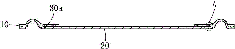
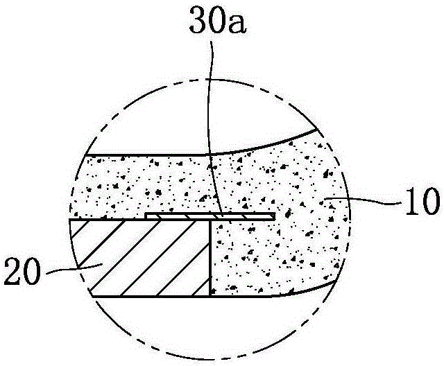
[0035] Such as figure 1 and figure 2 Commonly shown, a diaphragm, together with the voice coil constitutes the vibration system of the miniature sounder. Including the diaphragm body part 10 and the diaphragm center part 20 combined together, the diaphragm center part 20 is combined in the central position of the diaphragm body part 10 as an insert. In this embodiment, the diaphragm body part 10 and the diaphragm center part 20 combined by injection molding process. The part of the diaphragm center part 20 in the thickness direction is wrapped in the diaphragm body part 10. In this embodiment, the upper end surface of the edge part of the diaphragm center part 20 is wrapped in the diaphragm body part 10, that is, the diaphragm center part 20 The upper surface of the diaphragm body part 10 is wrapped, and the lower surface of the diaphragm center part 20 is exposed outside the diaphragm body part 10 . The upper end surface of the edge portion of the diaphragm center part 20...

Embodiment 2

[0039] This embodiment is basically the same as Embodiment 1, the difference is that:

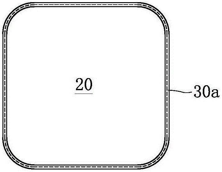
[0040] The reinforcing piece is a discontinuous segmented structure distributed along the edge of the center of the diaphragm.

[0041] Such as Figure 4 As shown, in this embodiment, the reinforcement 30 b is an arc structure, and there are four sections in total, and the four reinforcements 30 b are respectively located at the four corners of the diaphragm central portion 20 .

[0042]Such as Figure 5 As shown, the reinforcing piece 30c is a straight line structure, and there are four sections in total, and the four sections of the reinforcing piece 30c are respectively located at the four straight sides of the diaphragm center portion 20 .

[0043] The embodiment in which the reinforcement is a discontinuous segmental structure is not limited to the above two, and can also be distributed at the corner position and the straight edge position of the center of the diaphragm at the same t...

Embodiment 3

[0045] This embodiment is basically the same as Embodiment 1 or Embodiment 2, the difference is:

[0046] Such as Figure 6 As shown, the diaphragm center part 20 is wrapped in the diaphragm body part 10 as a whole, that is, the upper and lower end surfaces of the edge part of the diaphragm center part 20 are wrapped in the diaphragm body part, and the reinforcement part 30a is fixed on on one of the end surfaces.

[0047] In practical applications, reinforcing pieces can also be fixed on both the upper and lower end surfaces of the edge portion of the central part of the diaphragm, and the effect of fixing the reinforcing pieces on both end surfaces is better in preventing the diaphragm from cracking.


PUM


Abstract

The invention discloses vibration diaphragm and a miniature sounder with the vibration diaphragm and relates to the technical field of an electroacoustic product. The vibration diaphragm comprises a vibration diaphragm body part and a vibration diaphragm center part which are combined together through injection molding. The vibration diaphragm center part, as an insert, is combined at the center position of the vibration diaphragm body part. The edge parts of the vibration diaphragm center part are at least partially wrapped in the vibration diaphragm body part along a thickness direction. Reinforcement elements which stretch transversely and exceed the side surface of the edge part are connected with or are integrally arranged on the wrapped edge parts. The reinforcement elements stretch into the vibration diaphragm body part. According to the vibration diaphragm and the miniature sounder with the vibration diaphragm, the technical problem that in the prior art, the vibration diaphragm is liable to crack is solved. The crack defect will not occur in the vibration diaphragm and the vibration diaphragm of the miniature sounder with the vibration diaphragm, so that the reliability and stability of the miniature sounder are high, and the service life is long.

Description

technical field [0001] The invention relates to the technical field of electroacoustic products, in particular to a vibrating membrane and a miniature sound generator provided with the vibrating membrane. Background technique [0002] Miniature sound generator is an important acoustic component in portable electronic equipment, which is used to convert sound wave electric signal into sound signal, and is an energy conversion device. The micro sound generator usually includes a vibrating system and a magnetic circuit system. The vibrating system includes a combined diaphragm and a voice coil, wherein the vibrating diaphragm includes a vibrating diaphragm main part and a vibrating diaphragm central part which are combined by injection molding. [0003] At present, there is a diaphragm body made of soft colloidal material, such as a silicone diaphragm. The diaphragm body and the center of the diaphragm of this material can be combined through an injection molding process, that ...

Claims


Application Information

Patent Timeline
IPC IPC(8): H04R7/10H04R9/06H04R9/02
CPCH04R7/10H04R9/02H04R9/06H04R2400/11
Inventor 郭晓冬门春莲
Owner GOERTEK INC
Why Eureka
Try Eureka