Multifunctional knapsack

A multifunctional, backpack technology that can be used in small bags, clothing, travel or camping equipment, etc., to solve problems such as discomfort

Inactive Publication Date: 2016-12-21
徐浩哲
View PDF4 Cites 2 Cited by
  • Summary
  • Abstract
  • Description
  • Claims
  • Application Information

AI Technical Summary

Problems solved by technology

But when it comes to hot weather, whether it is an adult traveling with a backpack or a student carrying a schoolbag to school, it will make people feel uncomfortable because of the high temperature

Method used


Image

  • Multifunctional knapsack
  • Multifunctional knapsack
  • Multifunctional knapsack

Examples


Embodiment 1

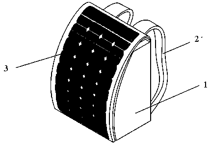
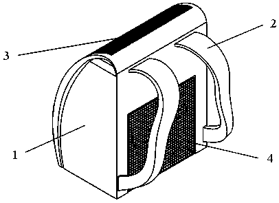
[0026] refer to figure 1 , figure 2 As shown, it is a schematic diagram of an embodiment of the present invention. The backpack is composed of a bag body (1) and a strap (2), and a heat sink (4) controlled by a switch is set on the side of the bag body (1) that fits the back of the human body. , the radiator (4) is connected to and powered by the solar panel (4) arranged on the side of the package body away from the back of the human body.

[0027] When using the backpack to go out, the sunlight irradiates the solar panel (3) to generate electric energy, and the electric energy is transmitted to the radiator (4) on the back, and the radiator (4) is activated by the switch, and the radiator (4) generates airflow to take away body heat , making people feel cool. At the same time, the solar battery panel (3) absorbs the heat energy radiated on the bag body (1), further reducing the temperature of the backpack.

[0028] Preferably, the solar panels (3) are in the form of thin ...

Embodiment 2

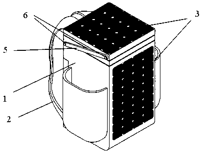
[0033] refer to image 3 , Figure 4 , Figure 5 , Figure 6 As shown, it is a schematic diagram of the second embodiment of the present invention. The backpack is composed of a bag body (1), a strap (2), a radiator (4), a solar panel (3), and a pole (5). (1) is a frame structure, in which a group of solar panels (3) and a radiator (4) are combined into a group of heat dissipation devices, and one end of the pole (5) is fixed to the frame of the package body (1) through the connecting shaft (6) Structurally, one end is clamped with the heat sink through the connecting card shaft (6). The heat sink is a solar panel (3) facing upward, and the radiator (4) is downward. The heat sink together with the support rod (5) can surround the connecting card The shaft (6) is turned over to the position above the backpacker's head, and the cooling device can adjust the blowing angle of the radiator (4) by connecting the clamp shaft (7).

[0034] Preferably, the strap (2) is made of brea...

Embodiment 3

[0037] refer to Figure 7 , Figure 8 , Figure 9 , Figure 10 As shown, it is a schematic diagram of the third embodiment of the present invention. The backpack is composed of a bag body (1), a strap (2), a radiator (4), a solar panel (3), and a pull rod (7). The bag body ( 1) is a frame structure, in which a group of solar panels (3) and a radiator (4) form a group of heat dissipation devices, one end of the tie rod (7) is fixedly connected to the frame structure of the package body (1), and the other end is connected to the heat dissipation device The shaft (6) is clamped, the radiator (4) is the radiator upward, and the solar panel (3) is the solar panel (3) downward, and the pull rod (7) is pulled up to drive the radiator to the limit height, and then surround Connect the card shaft (6) and turn the cooling device to the position above the backpacker's head, and the cooling device adjusts the blowing angle of the radiator (4) through the connecting card shaft (6).

[...


PUM


Abstract

A multifunctional knapsack is provided. The invention provides a knapsack used in summer having cool feeling. The knapsack comprises a bag body and a strap; a side, fitting body backs, of the bag body is provided with a heat radiator; the heat radiator is connected with a solar cell panel power supply and is controlled by a switch. The multifunctional knapsack has following functions in addition to the storage function: the additional heat radiator device can deliver air for users, the air can take away the heat of body backs so that the user feels cool and sweats less; the additional solar panel can provide clean energy for the heat radiator device and absorb the heat radiated on the knapsack at the same time which can cool the knapsack.

Description

technical field [0001] The invention relates to a daily necessities, in particular to an improvement of a backpack. Background technique [0002] With the continuous improvement of people's living and consumption standards, all kinds of backpacks have become indispensable daily necessities around people. But when it comes to hot weather, whether it is an adult traveling with a backpack or a student carrying a schoolbag to school, it will make people feel uncomfortable because of the high temperature. Contents of the invention [0003] In view of the above problems, the present invention provides a backpack that can feel cool even when used in summer. [0004] The technical solution is: a multifunctional backpack, which is composed of a bag body and a strap, and is characterized in that a radiator is arranged on the bag body, such as a computer notebook radiator in the prior art, and the radiator is connected to a fixed power supply and controlled by a switch run. [0...

Claims


Application Information

Patent Timeline
Patent Type & Authority Applications(China)
IPC IPC(8): A45F3/04A45C15/00A45C15/06
CPCA45F3/04A45C15/00A45C15/06
Inventor 徐浩哲熊曼
Owner 徐浩哲
Why Eureka
Try Eureka