A wet porous roller shutter electrostatic precipitator

An electrostatic precipitator and precipitator technology, applied in the direction of external electrostatic separator, electrostatic separation, electrode cleaning, etc., can solve the problems of high cost, corrosion of internal parts, complex structure, etc., and achieve simple structure, high work efficiency, and convenient maintenance Effect

Inactive Publication Date: 2017-08-25
WUHAN UNIV OF SCI & TECH
View PDF10 Cites 0 Cited by
  • Summary
  • Abstract
  • Description
  • Claims
  • Application Information

AI Technical Summary

Problems solved by technology

[0004] The wet electrostatic precipitator generally adopts the method of water spray overflow to form a layer of water film on the surface of the dust collecting plate, so that the dust and water deposited on the dust collecting plate are discharged through the ash hopper; the wet electrostatic precipitator Although it can effectively solve the problem of secondary dust, it still needs further improvement due to its complex structure, high cost, serious corrosion of internal parts, and low capture efficiency of fine particles.

Method used


Image

  • A wet porous roller shutter electrostatic precipitator
  • A wet porous roller shutter electrostatic precipitator

Examples


Embodiment 1

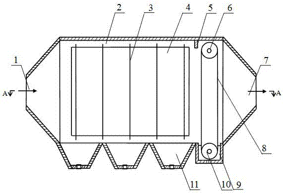
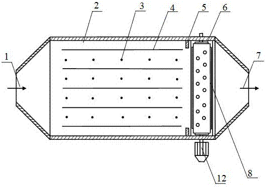
[0023] A wet type porous roller shutter electrostatic precipitator. like figure 1 and figure 2 As shown, the wet-type porous roller shutter electrostatic precipitator is composed of a dry-type electrostatic precipitator, a baffle (5) and a wet-type porous roller shutter dust catcher. The dry electrostatic precipitator is equipped with a wet-type porous roller shutter dust-catching device, one wet-type porous roller-screen dust-catching device is located on the side of the air outlet box (7), and the baffle (5) is located at the intake of the wet-type porous roller shutter dust-catching device. side.

[0024] like figure 1 and figure 2 As shown in the figure, the structure of the dry electrostatic precipitator is as follows: the left and right sides of the precipitator body (2) are correspondingly provided with an air intake box (1) and an air outlet box (7), and the bottom of the precipitator body (2) Three ash hoppers (11) are evenly arranged, the dust collector body (...

Embodiment 2

[0031] A wet type porous roller shutter electrostatic precipitator. Except the following technical parameters, all the other are the same as in Example 1:

[0032] The dry electrostatic precipitator is equipped with two wet-type porous roller shutter dust-catching devices, the two wet-type porous roller-screen dust-catching devices are located on one side of the air outlet box (7), and the two wet-type porous roller shutter dust-catching devices are parallel to each other;

[0033] The bottom of the dust collector body (2) is evenly provided with 2 or 4 ash hoppers (11);

[0034] The width of the front baffle is equal to 1.3~1.5 times the distance between the front side of the wet perforated roller shutter (8) and the front side plate of the main body; the width of the top baffle is equal to 1.3 times the minimum distance between the wet perforated roller blind (8) and the top plate of the main body ~1.5 times;

[0035] The width of the water tank (9) is equal to 1.4~1.5 tim...


PUM


Abstract

The invention relates to a wet porous roller shutter electrostatic precipitator. The technical solution is: the dry electrostatic precipitator is equipped with 1~2 wet porous roller shutter dust collectors, the wet porous roller shutter dust collector is located on the side of the air outlet box (7), and the baffle (5) is located on the wet porous roller shutter. The intake side of the dust collector. The bottom of the dust collector body (2) is provided with a water tank (9), the water tank (9) is located between the air outlet box (7) and the ash hopper (11), and the notch of the water tank (9) is flush with the bottom of the dust collector body (2); Drive drum (10) is housed in the water tank (9), and driven drum (6) is housed directly above the drive drum (10), and drive drum (10) and driven drum (6) pass around drive drum (10) and The wet porous roller blinds (8) between the driven rollers (6) are connected. The front side baffle, the top baffle and the rear side baffle of the baffle are successively fixed on the inner wall of the body front side plate, the inner wall of the body top plate and the inner wall of the body rear side plate. The device has the characteristics of simple structure, low cost, reliable operation and high dust removal efficiency.

Description

technical field [0001] The invention belongs to the technical field of electrostatic precipitators. Specifically, it is a wet-type porous roller shutter electrostatic precipitator. Background technique [0002] At present, various types of dust removal devices are mainly used to separate and capture dust from dust-laden flue gas, among which electrostatic precipitators are widely used. [0003] The dry electrostatic precipitator uses corona wire discharge to charge the dust in the flue gas, and the charged dust moves to the dust collecting plate under the action of the electric field force and is collected, so as to separate the dust from the flue gas. Purpose, the cleaning method generally adopts mechanical rapping. Although it has the advantages of large amount of flue gas, low resistance, and high dust removal efficiency, it also has some shortcomings, mainly because of its low capture efficiency of fine particles, and In the process of rapping and cleaning, it is easy ...

Claims


Application Information

Patent Timeline
Patent Type & Authority Patents(China)
IPC IPC(8): B03C3/08B03C3/16B03C3/78
CPCB03C3/08B03C3/16B03C3/78
Inventor 陈旺生李泽胡发立李富智
Owner WUHAN UNIV OF SCI & TECH
Why Eureka
Try Eureka