Machining method of cylindrical reinforcement cage

A processing method and technology of steel cages, applied in the direction of wire processing, wire manufacturing of ring nets, other household appliances, etc., can solve the problems of confusing steel keels, prone to confusion and defective products, time-consuming and labor-intensive, etc. To achieve the effect of improving construction efficiency, reducing labor intensity and construction period, firmness and structural performance are stable and reliable

Active Publication Date: 2016-12-21
赵光林
View PDF14 Cites 6 Cited by
  • Summary
  • Abstract
  • Description
  • Claims
  • Application Information

AI Technical Summary

Problems solved by technology

This process is time-consuming and labor-intensive, and the steel keels of different shapes and sizes often make workers confused, which is prone to confusion and defective products
At present, there is no mechanized processing equipment for prefabricated wall module steel keel on the market
Therefore, it can be said that the processing of the reinforced keel of the prefabricated wall module is the bottleneck problem restricting the practical application of the prefabricated wall module

Method used


Image

  • Machining method of cylindrical reinforcement cage
  • Machining method of cylindrical reinforcement cage
  • Machining method of cylindrical reinforcement cage

Examples


Embodiment Construction

[0053] The present invention will be described in further detail below in conjunction with specific embodiments and accompanying drawings.

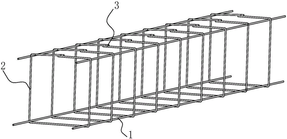
[0054] The core technical problem to be solved by the present invention is exactly how to process figure 1 Cylindrical reinforcement cage shown. The reinforcement cage includes four longitudinal reinforcement bars 1 along the length direction, which are formed by connecting a plurality of stirrup bars 2 . There can also be more reinforcing bars along the length direction, for example, adding a longitudinal reinforcing bar 1 to each of the four faces of the four columns, then there are 8 reinforcing bars in the longitudinal direction of the reinforcing cage; the structural strength of the reinforcing cage can be further improved .

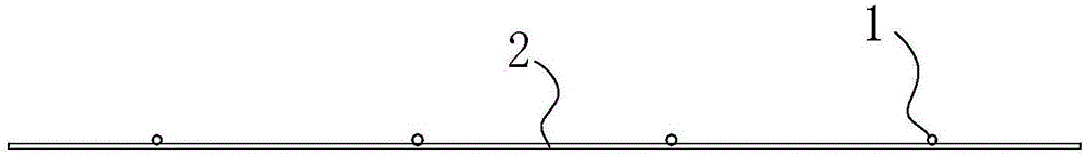
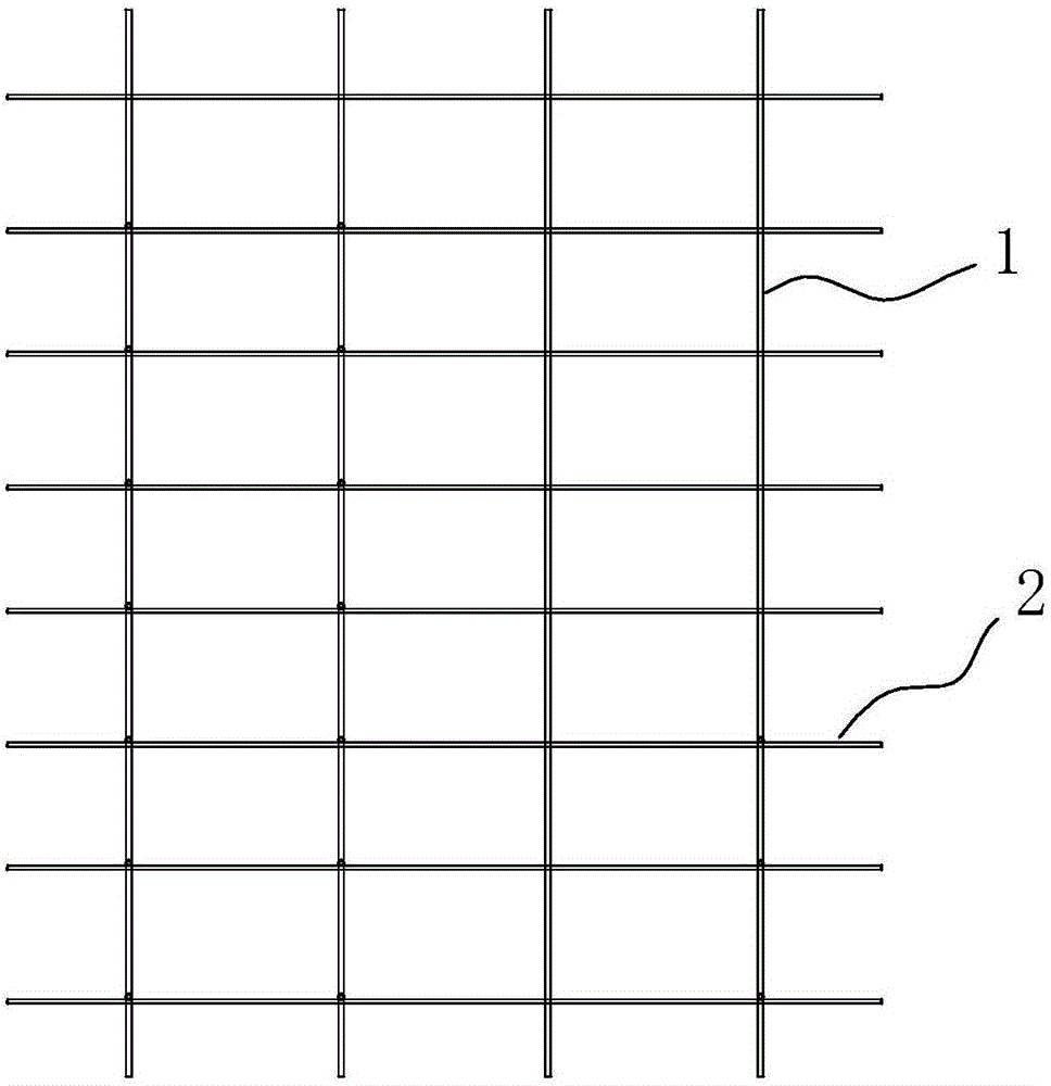
[0055] The method of processing the reinforcement cage is to make the combined figure 2 , 3 The sheet steel mesh shown. There are longitudinal steel bars 1 arranged along the length direction and stirrup ...


PUM


Abstract

The invention relates to machining methods and devices of a cylindrical reinforcement cage. The machining method of the cylindrical reinforcement cage comprises the steps that sheet-shaped reinforcement meshes are machined; the sheet-shaped reinforcement meshes are bent into deep U shapes or shallow U shapes; then, the middle portions of the shallow-U-shaped reinforcement meshes are bent again to form U-shaped structures, the reinforcement meshes are made to form cylinders in a surrounding manner, the folded portions of bent reinforcing steel bars are connected, and then the reinforcement cage is formed; or, the two sides of each deep-U-shaped reinforcement mesh is bent oppositely to form a cylinder, the folded portions of the bent reinforcing steel bars are connected, and then the reinforcement cage is formed. The machining method of the cylindrical reinforcement cage has the beneficial effects that the sheet-shaped reinforcement meshes are obtained through a mesh welding machine, the reinforcement meshes are bent, and then the cylindrical reinforcement cage is formed; and the upper latitude reinforcing steel bars and the lower latitude reinforcing steel bars of the cylindrical reinforcement cages are connected correspondingly, and then continuous reinforcement cages can be rapidly machined, and then the continuous reinforcement cages are cut into needed steel reinforcing bar keels or are cut and then connected into the needed steel reinforcing bar keels. The machining method of the cylindrical reinforcement cage solves the bottleneck problem that in a prefabricated wall module, the machining efficiency of the steel reinforcing bar keels is low and creates conditions for wide application of the prefabricated wall module.

Description

[0001] This application is a divisional application with application date: 2015-07-23, application number: 201510437171.5, and invention name: "processing method and equipment for cylindrical steel cage". technical field [0002] The invention relates to construction machinery and equipment, in particular to a processing method for a cylindrical reinforcement cage. Background technique [0003] With the growth of global population and the rapid development of society, the depletion of earth's resources and the deterioration of the environment have become severe challenges for human beings. The construction industry is a traditional high-consumption and high-pollution industry; it has brought enormous pressure on environmental degradation. [0004] The construction industry needs to use a large number of sintered bricks or unburned bricks to build walls. However, clay resources are limited, and the extensive use of sintered bricks not only increases sintering energy consumpt...

Claims


Application Information

Patent Timeline
Patent Type & Authority Applications(China)
IPC IPC(8): B21F31/00
CPCB21F31/00
Inventor 赵光林赵卫强赵纪国赵鹏昆
Owner 赵光林
Why Eureka
Try Eureka