Laser impact welding device and laser impact welding method

A laser shock and welding device technology, applied in laser welding equipment, welding equipment, metal processing equipment and other directions, can solve the problems of reducing welding reliability, affecting welding efficiency, difficult to automate, etc., to achieve high joint surface quality, welding device Simple and efficient welding results

Inactive Publication Date: 2016-12-21
JIANGSU UNIV
View PDF7 Cites 25 Cited by
  • Summary
  • Abstract
  • Description
  • Claims
  • Application Information

AI Technical Summary

Problems solved by technology

The difference is that explosive welding is generally applied to large-sized flat plate welding, and there are significant defects such as large sound pollution and difficulty in automation, which restrict the wide application of explosive welding technology
Electromagnetic pulse welding can achieve linear and circumferential welding, and the typical welding width is at the millimeter to centimeter level. The disadvantage is that the welding material must have good electrical conductivity, which is the most important reason for limiting the development of this welding technology.
In this process, the workpiece needs to be closely bonded to the flyer with the same area through the bonding medium. If the flyer and the workpiece are not tightly bonded, the flyer and the workpiece are prone to welding, which reduces the reliability of welding.
In addition, a certa...

Method used


Image

  • Laser impact welding device and laser impact welding method
  • Laser impact welding device and laser impact welding method
  • Laser impact welding device and laser impact welding method

Examples


Embodiment Construction

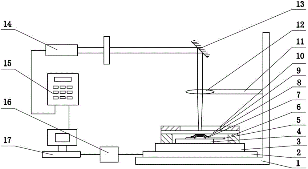
[0033] The present invention will be further described below in conjunction with the accompanying drawings and specific embodiments, but the protection scope of the present invention is not limited thereto. Such as figure 1 As shown, a laser shock welding device includes a three-coordinate mobile platform device, a laser generating device, a welding device and a control device;

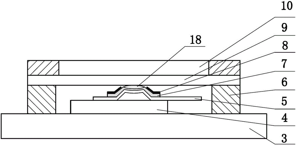
[0034] The three-coordinate mobile platform 2 is located on the bottom plate of the L-shaped base 1, the focusing lens 12 is connected to the focusing lens fixing rod 11, and the focusing lens fixing rod 11 is installed on the side plate of the L-shaped base 1; the pulse laser 14 The emitted laser beam is irradiated on the black paint layer 8 above the inverted trapezoidal step in the upper plate 5 through the reflector 13 and the focusing lens 12 .

[0035] Described laser generating device comprises pulse laser 14, reflecting mirror 13, focusing lens 12, focusing lens fixed rod 11; Paint layer 8, ...


PUM

PropertyMeasurementUnit
Thicknessaaaaaaaaaa
Thicknessaaaaaaaaaa
Pulse widthaaaaaaaaaa

Abstract

The invention discloses a laser impact welding device and a laser impact welding method, relating to the field of high speed impact welding. The laser impact welding device comprises a laser generating device, a welding device, a three-coordinate moving platform device and a control device, wherein an inverted trapezoidal step is machined at an upper-layer plate in the welding device, thus being convenient for forming an impact angle and an impact speed required by impact welding. According to the laser impact welding device and the laser impact welding method, the limitation of a conventional laser impact welding method that a certain flying distance is required to be given between an upper-layer plate and a lower-layer plate can be overcome, and the problem that the dimension of the upper-layer plate is limited by the dimension of a laser spot can be solved. In addition, the welding device is simple, the welding efficiency is high, the surface quality of a joint is high, and the welding device and the welding method are applicable to efficient and reliable connection of micro devices.

Description

technical field [0001] The invention relates to the field of high-speed impact welding, in particular to a laser impact welding device and a method thereof. Background technique [0002] Laser shock welding is a relatively new high-speed impact welding technology. The basic principle of welding is the same as that of explosive welding and magnetic pulse welding. It uses two metal plates to collide at high speed at an appropriate impact angle. When the upper plate and the lower plate When the collision angle and impact velocity exceed critical values, solid-state metallurgical bonding occurs under the action of strong plastic shear deformation at the collision interface and high temperature and pressure. The difference is that explosive welding is generally applied to large-sized flat plate welding, and there are significant defects such as large sound pollution and difficulty in realizing automation, which restrict the wide application of explosive welding technology. Elect...

Claims


Application Information

Patent Timeline
IPC IPC(8): B23K26/21B23K26/0622B23K26/60B23K26/70
CPCB23K26/21B23K26/0624B23K26/60B23K26/702
Inventor 高帅刘会霞马友娟王霄李聪李立银孙先庆沙朝飞沈宗宝
Owner JIANGSU UNIV
Why Eureka
Try Eureka