A kind of cutting edge processing technology

A technology for processing technology and knives, which is applied in the field of tool edge processing technology, can solve the problems of rough cutting edge, reduce the wear resistance of the cutting edge, and deep roughness, etc., and achieve the reduction of cutting edge chipping, high durability requirements, The effect of improving durability

Active Publication Date: 2018-03-30
锑玛(苏州)精密工具股份有限公司
View PDF5 Cites 0 Cited by
  • Summary
  • Abstract
  • Description
  • Claims
  • Application Information

AI Technical Summary

Problems solved by technology

[0004] 1. Only use a file or oil stone for processing. After production, the cutting edge of the tool is detected on a magnifying inspection instrument. There are obvious jagged lines, the lines are very thick and deep, and the effect of improving the cutting edge cannot be achieved.
[0005] 2. Only use polishing sand for processing. After production, the cutting edge of the tool is detected on a magnifying inspection instrument. There are obvious small pits, and the pits are too large and too many, which cannot achieve the effect of improving the cutting edge.
[0006] 3. Use the combination of file and polishing sand, oil stone and polishing sand, file and oil stone and polishing sand to process. The jagged lines and small pits are slightly improved, but the jagged lines and small pits still exist, and they are still relatively thick. , deeper, more, larger, and after processing in combination, jagged lines and small pits exist at the same time, which reduces the wear resistance of the cutting edge
[0007] Combining the above forms, the cutting edge made by using the above tools is detected on the magnifying inspection instrument. The cutting edge is relatively rough, with obvious jagged lines and tiny pits. The powdery iron filings generated by the cutting tool during use will accumulate In the lines and pits, because the iron filings are in a high temperature state during processing, if they accumulate on the cutting edge, the cutting edge will be in a high temperature state for a long time, and small cracks will appear on the cutting edge, the cracks will continue to expand, and the cutting edge will chip. , resulting in the tool not being able to continue to be used, the wear resistance of the tool edge cannot be improved, and ultimately the durability of the tool cannot be improved

Method used


Image

  • A kind of cutting edge processing technology
  • A kind of cutting edge processing technology
  • A kind of cutting edge processing technology

Examples


Embodiment 1

[0029] A kind of tool edge processing technology described in the present invention, comprises the following steps:

[0030] (a) Process the shape of the tool with a lathe according to the size of the drawing, hold the tool in the left hand, place the tool on the fixed seat so that the cutting edge of the cutting tool is parallel to the horizontal reference line of the fixed base, and process on the cutting edge of the cutting tool at a constant speed with the right hand ;

[0031] (b) Then put the tool processed with the file into the polishing machine for polishing, set the speed of the polishing machine to 45r / s, and set the polishing time to 10 minutes clockwise and 2 minutes counterclockwise;

[0032] (c) Clamp the ultra-fine fluff brush to the wheel brush instrument, set the speed of the wheel brush instrument to 200r / s, and set the time to 1.5 minutes, place the tool on the workbench under the ultra-fine fluff brush for fine polishing , After processing, just remove th...

Embodiment 2

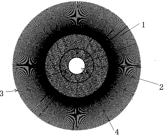
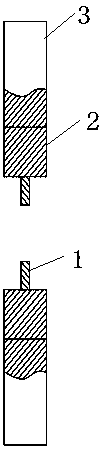
[0042] The ultra-fine fluff brush in step (c) described in this embodiment includes a clamping positioning surface 1, a base body 2,

[0043] Superfine velvet 3, the clamping positioning surface 1 is a ring, the middle position is a clamping matching hole 4, the base 2 is a ring setting outside the clamping positioning surface 1, and the ultrafine velvet 3 is evenly arranged on the base 2 outer edge.

[0044] The material of the superfine fleece 3 in this embodiment is plastic.

[0045] The material of the base 2 in this embodiment is iron.

[0046] In this embodiment, the diameter of the clamping matching hole 4 is 20 mm, the thickness of the clamping positioning surface 1 is 3 mm, the inner diameter of the clamping positioning surface 1 is 20 mm, and the outer diameter is 40 mm.

[0047] In this embodiment, the thicknesses of the substrate 2 and the superfine fleece 3 are the same as 15mm, the inner diameter of the substrate 2 is 40mm, and the outer diameter is 75mm, and t...


PUM

PropertyMeasurementUnit
diameteraaaaaaaaaa
thicknessaaaaaaaaaa
thicknessaaaaaaaaaa

Abstract

The invention provides a tool edge processing technology. The tool edge processing technology comprises the following steps that 1, a left hand holds a tool, the tool is placed on a fixed base to enable a tool edge to be parallel to the horizontal datum line of the fixed base, and a right hand holds a file to machine the tool edge; 2, the tool machined with the file is placed in a polishing machine, wherein the revolving speed of the polishing machine is set as 45 r / s, the clockwise polishing time is set as 10 minutes, and the anticlockwise polishing time is set as 2 minutes; 3, a superfine velvet wheel brush is clamped to a wheel brush instrument, the tool is placed on a working table arranged under the superfine velvet brush to be subjected to finish polishing machining, and after machining is finished, the tool is taken down, wherein the revolving speed of the wheel brush instrument is set as 200 r / s, and the time is set as 1.5 minutes. After the tool is machined through the processes, sawtooth-shaped grain and small cracks of the tool edge are detected on an amplification detector, the grain and pits obviously become shallower, smaller and fewer, and some tools even can achieve a grain-free and pit-free state.

Description

technical field [0001] The invention relates to the technical field of tool processing, in particular to a tool edge treatment process. Background technique [0002] As customers' requirements for tool durability continue to increase, the requirements for tool wear resistance are getting higher and higher. For tools with high durability requirements, the wear resistance of tool raw materials, tool coatings, and The wear resistance of the cutting edge has higher requirements. The patent of the present invention has made obvious improvements to the edge treatment of the tool to improve the durability of the edge of the tool, thereby meeting the high durability requirements of customers. [0003] General tool edge treatment tools include files, whetstones, and polishing sand. The edge treatment methods are divided into processing with a single tool or a combination of multiple tools. The following are the specific situations of using several tools: [0004] 1. Only use a fil...

Claims


Application Information

Patent Timeline
Patent Type & Authority Patents(China)
IPC IPC(8): B24B1/00B24B29/02B24D13/10B24D13/20B23P15/28
CPCB23P15/28B24B1/00B24B29/02B24D13/10B24D13/20
Inventor 李振丰奚旭东孔小波张明敏
Owner 锑玛(苏州)精密工具股份有限公司
Why Eureka
Try Eureka