Oilless vacuum single pump

A vacuum and single-pump technology, applied in the direction of pumps, pump components, rotary piston type/oscillating piston type pump components, etc., to achieve the effects of stable positive and negative pressure, clean energy, and stable suction and blowing

Inactive Publication Date: 2016-12-21
NANTONG BEIKE VACUUM MACHINERY CO LTD
View PDF7 Cites 2 Cited by
  • Summary
  • Abstract
  • Description
  • Claims
  • Application Information

AI Technical Summary

Problems solved by technology

For the vacuum pump with this feature, there is no report in the existing patent literature

Method used


Image

  • Oilless vacuum single pump
  • Oilless vacuum single pump
  • Oilless vacuum single pump

Examples


Embodiment Construction

[0024] The present invention will be further described below in conjunction with the drawings.

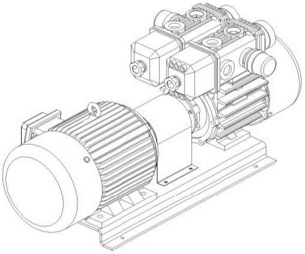
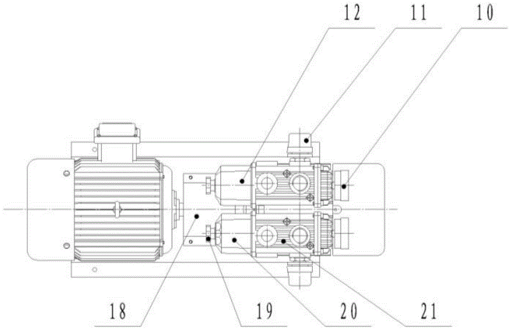
[0025] Such as Figure 2-4 , Is an oil-free vacuum single pump, including a base 17 and a compression cylinder 13 installed on the base 17, the compression cylinder is connected to the motor 1 through a coupling 16; one end of the compression cylinder 13 is equipped with a fan device, and the top of the compression cylinder 13 Connect the muffler equipment; the rotor 5 inside the compression cylinder 13 has a sliding plate group. At the same time, in order to improve this new oil-free vacuum pump, the present invention makes corresponding changes to various components.

[0026] Such as figure 2 , The coupling cushion 2 is installed on the coupling 16 to make the connection between the motor and the compression cylinder more stable. At the same time, a bearing gland 15 is installed at the entrance of the compression cylinder 13 to further ensure the stability of the connection. At the ...


PUM


Abstract

The invention discloses an oil-free vacuum single pump, which comprises a base and a compression cylinder installed on the base, the compression cylinder is connected to a motor through a coupling; a fan device is installed at one end of the compression cylinder, and The top of the compression cylinder is connected to the muffler equipment; the rotor inside the compression cylinder has a slide set. The invention solves the problem of high operating noise of the traditional oil-type vacuum pump. It is driven by an electric motor and has a slide group on the rotor. The suction and blowing of the compressed air cylinder are stable, and it is especially suitable for indoor machines such as printing machines and photoplate-making machines. , and can be widely used in vacuum lifters, liquid mixers, etc.

Description

Technical field [0001] The invention relates to an oil-free single vacuum pump, belonging to the technical field of vacuum pump structures. Background technique [0002] A vacuum pump is a device that can obtain vacuum conditions and is widely used in various fields of industrial production. The disadvantages of the existing vacuum pumps are complex structure, many parts, high manufacturing costs, difficult daily maintenance and disassembly, adopting a through-type eccentric spindle structure, high leakage rate, small compression, many rotating parts, high friction coefficient, and high noise. Need to increase the motor dynamic rate accordingly. One of them has a wide range of applications. The more traditional vacuum pump is an oil vacuum pump, but because the vacuum pump introduces a large amount of dust, water vapor, etc. during the suction process, the oil supply device is usually blocked, and a lot of cost is required to improve the filter device; In addition, the existing...

Claims


Application Information

Patent Timeline
Patent Type & Authority Applications(China)
IPC IPC(8): F04C25/02F04C29/06F04C29/04
Inventor 姚新建
Owner NANTONG BEIKE VACUUM MACHINERY CO LTD
Why Eureka
Try Eureka