Open type photoelectric effect experimental apparatus and operation method thereof

A photoelectric effect and operating method technology, applied in instruments, educational appliances, teaching models, etc., can solve problems such as difficulty in expanding the experimental content, and achieve the effect of small spatial distribution of light energy, uniform light intensity distribution, and good linear relationship.

Pending Publication Date: 2016-12-21
TONGREN UNIV
View PDF10 Cites 7 Cited by
  • Summary
  • Abstract
  • Description
  • Claims
  • Application Information

AI Technical Summary

Problems solved by technology

[0003] The traditional photoelectric effect experiment instrument can only complete simple verification exp

Method used


Image

  • Open type photoelectric effect experimental apparatus and operation method thereof
  • Open type photoelectric effect experimental apparatus and operation method thereof

Examples


Example Embodiment

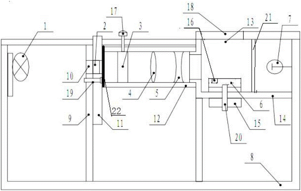
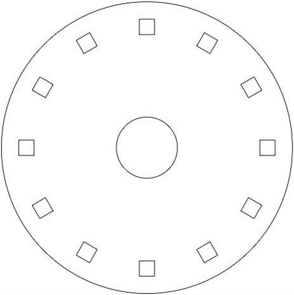
[0050] Embodiment 1: as Figure 1-Figure 2As shown, an open photoelectric effect experiment apparatus includes an LED light source 1, a plurality of color filters 2 of different colors, an aperture 3, a convex lens 4, a concave lens 5, a sample stage 6 and a photoelectric tube 7, and the LED light source 1 is installed in a sealed On the left side wall of the housing 8, a light blocking plate 9 is arranged in the middle of the housing 8, and the light blocking plate 9 is provided with a light transmission hole 10 facing the LED light source 1, and a plurality of optical filters 2 are installed on the turntable 11 to ensure the rotation of the turntable 11 After each filter 2 can be aligned with the light transmission hole 10, the turntable 11 is rotatably installed on the right side of the light blocking plate 9, and the aperture 3, the convex lens 4 and the concave lens 5 are installed in the sleeve 12 from left to right in turn and ensure that The center is facing the light ...

Example Embodiment

[0061] Embodiment 2: a kind of operation method of open type photoelectric effect experiment instrument, this method comprises the following steps:

[0062] (1) Turn on the power supply of the tester and LED mercury lamp, and preheat for 5-8 minutes;

[0063] (2) Adjust the aperture to the closed state, the sample cell window is empty, and rotate the sample cell sample turntable so that the sample cell window is on the optical path and the light passes freely;

[0064] (3) Connect the voltage input terminal of the photocell dark box with the voltage output terminal of the tester with a special connection line;

[0065] (4) After the instrument is fully warmed up, zero-adjust before testing; please disconnect the electrical box from the photocell first, and perform zero-adjustment and calibration on the micro-current test of the tester when there is no current input from the photocell;

[0066] (5) Connect the current output terminal K of the photocell dark box with the microc...


PUM


Abstract

The invention discloses an open type photoelectric effect experimental apparatus and an operation method thereof. The open type photoelectric effect experimental apparatus comprises an LED light source, a plurality of optical filters of different colors, an aperture, a convex lens, a concave lens, a sample bench, and a photoelectric tube. The LED light source is disposed on a left side wall of a sealed housing, and the middle part of the housing is provided with a baffle. The baffle is provided with a light transmitting hole aligned with the LED light source. The plurality of optical filters are disposed on a rotating disc, and every optical filter is guaranteed to be aligned with the light transmitting hole, after the rotating disc is rotated. The rotating disc is rotatably disposed on the right side of the baffle, and the aperture, the convex lens, and the concave lens are, from left to right, sequentially disposed on a sleeve, and the centers are guaranteed to be aligned with the light transmitting hole. The right end of the sleeve is connected with an outer side wall of a sample testing cavity, and the sample bench is disposed in the sample testing cavity. The right side of the sample bench is provided with the photoelectric tube. Light energy space distribution difference is small, linear relation is good, and experiment effect is good. By comparing with a mercury lamp, non-toxic performance is provided. Voltage is low, energy is saved, a heating value is small, thermal radiation is reduced, and testing influences are small.

Description

technical field [0001] The invention belongs to the technical field of photoelectric effect test devices, and relates to an open photoelectric effect test device and an operating method thereof. Background technique [0002] The photoelectric effect experiment needs to measure the Planck constant and the volt-ampere characteristic of the phototube to verify the relationship between the photocurrent and the light intensity. The traditional photoelectric effect experiment instrument only measures Planck's constant. When the traditional photoelectric effect experiment instrument measures the relationship between saturation current and light intensity, due to the small light-emitting surface of the ordinary mercury lamp light source, the spatial distribution of light energy varies greatly. The linear relationship is very poor and the experimental effect is poor. Metal mercury is poisonous, and mercury lamps have high operating voltage, high power consumption, and high heat gen...

Claims


Application Information

Patent Timeline
IPC IPC(8): G09B23/22G09B23/18
CPCG09B23/18G09B23/22
Inventor 陈琳欧永康李勇冉茂武宋谋胜黄帅
Owner TONGREN UNIV
Why Eureka
Try Eureka