Self-damping double-reel pay-off device and application method thereof

A technology with built-in damping and wire-releasing devices, which is applied to conductor/cable supply devices, electrical components, circuits, etc., can solve problems such as difficult maintenance, inappropriate magnetic powder motors, and difficulty in ensuring power supply, so as to increase twisting tension and increase Scope of application, effect of increasing aesthetics

Inactive Publication Date: 2016-12-21
ZHENGZHOU YIFANG ELECTRIC
View PDF6 Cites 8 Cited by
  • Summary
  • Abstract
  • Description
  • Claims
  • Application Information

AI Technical Summary

Problems solved by technology

The magnetic powder motor is also not suitable, because it is a mobile pay-off frame, so it is difficult

Method used


Image

  • Self-damping double-reel pay-off device and application method thereof
  • Self-damping double-reel pay-off device and application method thereof
  • Self-damping double-reel pay-off device and application method thereof

Examples


Embodiment 1

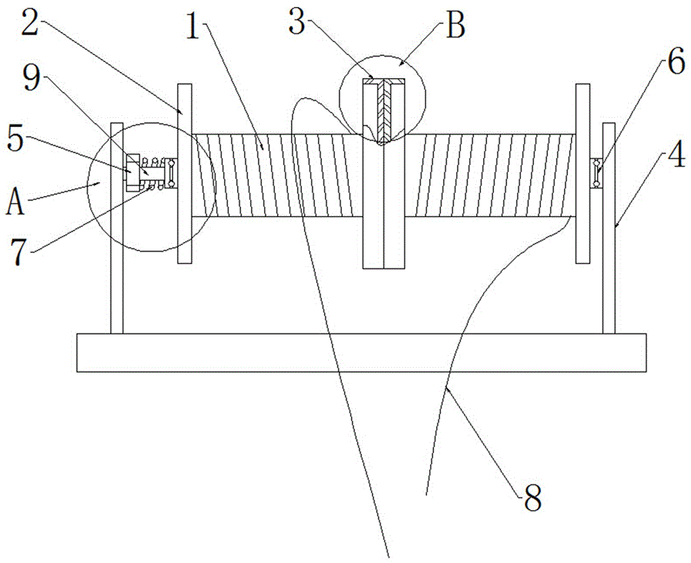
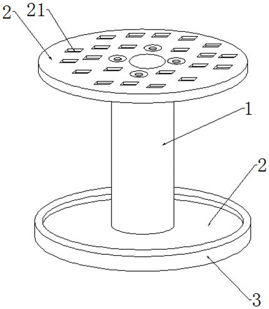
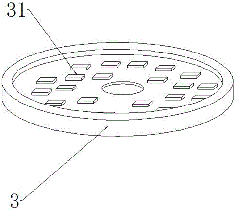
[0020] Embodiment 1 A double-disk pay-off device with its own damping, see Figure 1-3 : Including the installation shaft 9, the pay-off reel 1, and the two sets of pay-off reels 1 that are wound in opposite directions with the wire core 8 contradicting each other and assembled on the installation shaft 9, and the friction plates 3 are correspondingly provided on the end faces of the two groups of pay-off reels 1 that conflict with each other The installation shaft 9 is correspondingly connected to the installation bracket 4, and the installation shaft 9 is provided with a pressure regulating structure corresponding to the pay-off reel 1.

[0021] The two ends of the pay-off reel 1 are correspondingly provided with a limit disc 2, and the friction plate 3 is correspondingly set on the limit disc 2 through the installation groove matching the end surface of the limit disc 2; the side wall of the limit disc 2 is distributed with blind holes 21 , the inner wall of the friction pl...

Embodiment 2

[0030] Embodiment 2 A double-disk pay-off device with its own damping, see Figure 1-3 : A double-disk pay-off device with self-damping, comprising an installation shaft 9, a pay-off reel 1, two sets of pay-off reels 1 with wire cores 8 reversely wound against each other and assembled on the installation shaft 9, the two groups of release reels 1 The friction plates 3 are correspondingly provided on the conflicting end surfaces of the wire reels 1; the installation shaft 9 is correspondingly connected to the installation bracket 4, and the installation shaft 9 is provided with a pressure regulating structure corresponding to the pay-off reel 1.

[0031] The two ends of the pay-off reel 1 are correspondingly provided with a limit disc 2, and the friction plate 3 is correspondingly set on the limit disc 2 through the installation groove matching the end surface of the limit disc 2; the side wall of the limit disc 2 is distributed with blind holes 21 , the inner wall of the frict...


PUM


Abstract

The invention relates to a self-damping double-reel pay-off device and an application method thereof. The self-damping double-reel pay-off device comprises an installation shaft and pay-off reels, wherein the two sets of pay-off reels with wire cores winding in opposite directions are assembled on the installation shaft in a manner of pressing against each other, the pressing end surfaces of the two sets of pay-off reels are each provided with a friction plate correspondingly; the installation shaft is connected on an installation bracket correspondingly, and the installation shaft is provided with a pressure adjusting structure corresponding to one pay-off reel. By arranging the friction plates, the resistance of the adjacent pay-off reels can be increased, thereby increasing twisting tension; and by utilizing the principle that forces of friction interact with each other, the adjacent pay-off reels have the same resistance, thereby effectively improving the wire core twisting quality.

Description

technical field [0001] The invention relates to a double-disc tension pay-off device, in particular to a double-disc pay-off device with self-damping and a use method thereof. Background technique [0002] Wire stranding production in the wire and cable industry often requires the use of pay-off devices. In the process of stranding wire cores, in order to ensure the synchronization of two or more pay-off reels, it is necessary to implement core tension control on the pay-off reels to ensure stranding quality. , the existing tension control device generally controls the tension through a wear-resistant belt or a magnetic powder motor. When the above-mentioned device is used for double-disc pay-off, problems such as excessive floor space often occur. In terms of tension adjustment, the tension adjustment of the wear-resistant belt is unreliable. Now it is adjusted properly, but it will be too tight or too loose after a while. The magnetic powder motor is also not suitable, be...

Claims


Application Information

Patent Timeline
IPC IPC(8): H01B13/00H01B13/02
CPCH01B13/0003H01B13/0207
Inventor 侯金保常正卿吉志林
Owner ZHENGZHOU YIFANG ELECTRIC
Why Eureka
Try Eureka