Installation structure of current sampling resistor

A technology of installation structure and current sampling, applied in the direction of resistor installation/support, resistance terminal/electrode, improvement of basic electrical components, etc. Sampling values ​​and other issues to achieve the effect of avoiding differences, ensuring accuracy, and ensuring the accuracy of resistance values

Inactive Publication Date: 2016-12-21
浙江朗科智能电气有限公司
View PDF5 Cites 2 Cited by
  • Summary
  • Abstract
  • Description
  • Claims
  • Application Information

AI Technical Summary

Problems solved by technology

[0002] Because of the advantages of small temperature drift, high power, and high cost performance of Kang and manganese copper wires, Kang and manganese copper wires are often used as sampling resistors for large current sampling. The above sampling resistors are directly plugged into the circuit board. The way the grooves are formed by deformation on the side determines the depth of insertion on the circuit board, but due to the limited effect of the grooves, different insertion forces will cause different insertion depths of the two feet on the circuit board, resulting in The resistance value of the sampling resistor is different from the design value, which affects the sampling value of the current, that is, the installation method of the current sampling resistor made of Kang and manganese copper wire will make the sampling current value inaccurate and affect the performance of the entire system, which cannot meet Sampling Current Accuracy Requirements

Method used


Image

  • Installation structure of current sampling resistor
  • Installation structure of current sampling resistor
  • Installation structure of current sampling resistor

Examples


Embodiment 1

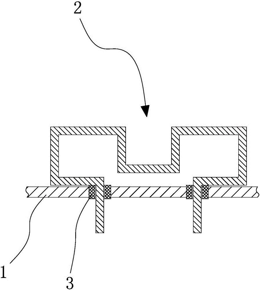
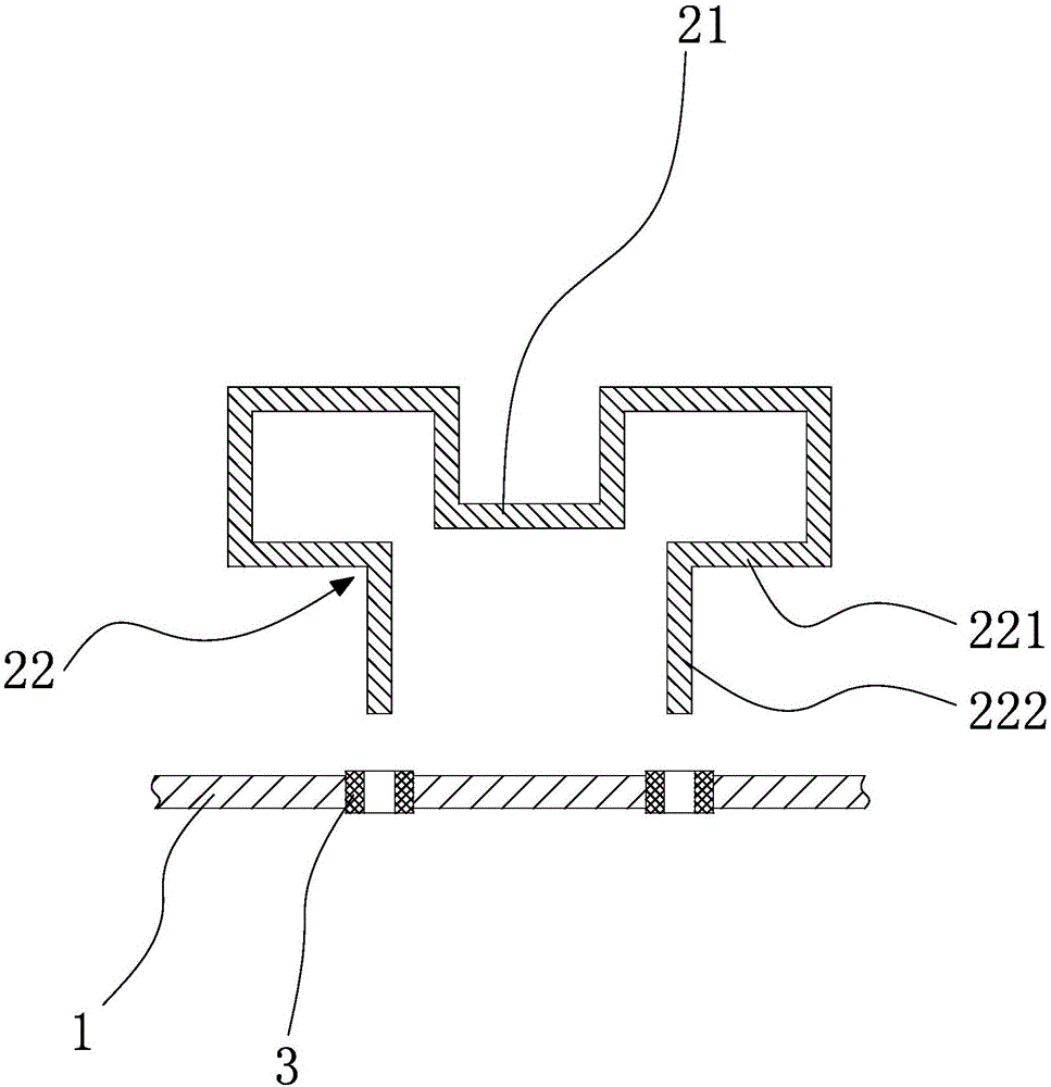
[0018] The first embodiment includes a PCB board 1 and a current adopting resistor 2 , and the current adopting resistor 2 is connected to the PCB board 1 through a pad 3 . The current adopting resistor 2 includes a sampling terminal 21 and two wires 22 arranged on both sides of the sampling terminal 21. The wires 22 include a first line segment 221 and a second line segment 222. One end of the first line segment 221 is connected to the sampling end 21, and the second line segment 221 is connected to the sampling end 21. The other end of the line segment 221 is connected to the second line segment 222, the setting direction of the first line segment 221 is parallel to the board surface of the PCB board 1, and the setting direction of the second line segment 222 is perpendicular to the board surface of the PCB board 1, respectively belonging to two The lengths of the two first line segments 221 of one wire 22 are equal, and the lengths of the two second line segments 222 belongi...

Embodiment 2

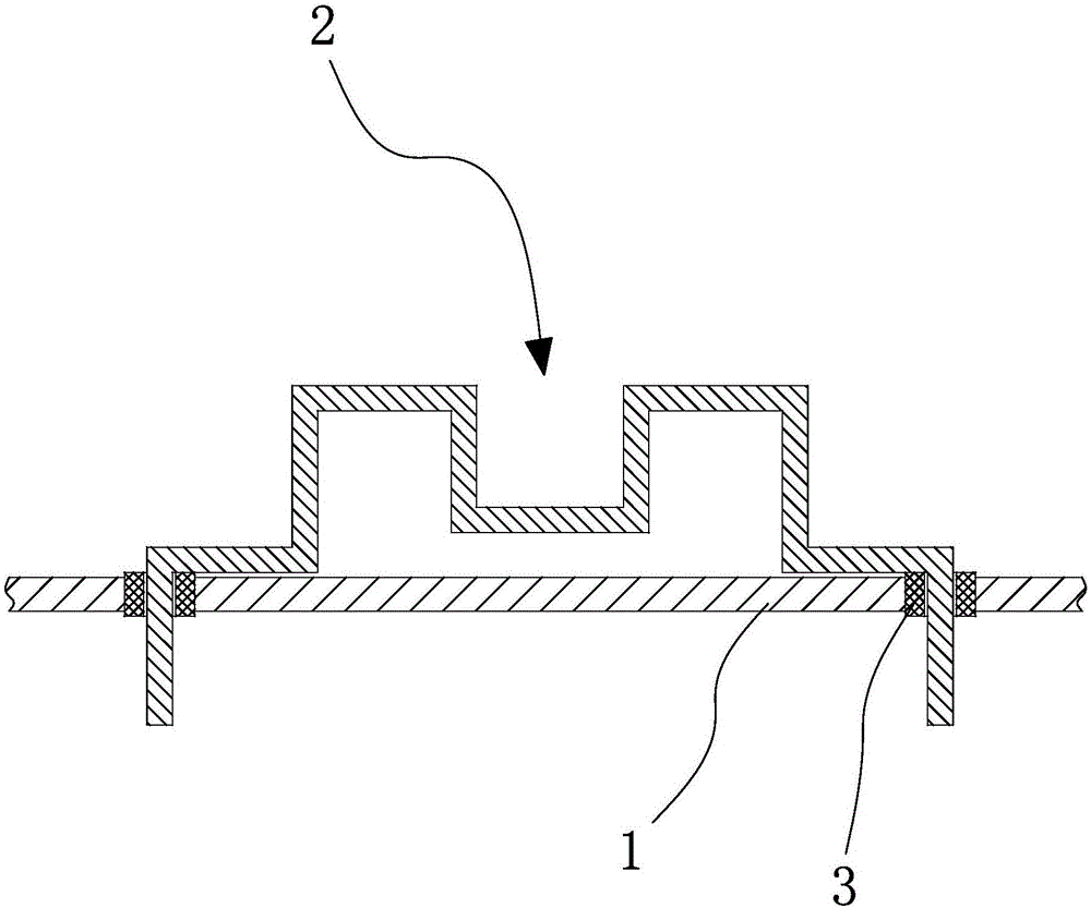
[0021] The structure of the second embodiment is basically the same as that of the first embodiment, the difference is that the second line segment 222 in the second embodiment is bent outward and downward from the first line segment 221 to be suitable for two via holes PCB boards with large spacing 1.


PUM


Abstract

The invention provides an installation structure of a current sampling resistor, belongs to the technical field of electronic products, and aims at solving the problem that a current sampling value of an existing current sampling resistor is inaccurate due to an insecure installation mode. The installation structure of the current sampling resistor comprises a current using resistor inserted into a PCB, wherein the current using resistor comprises a sampling end and two wire rods arranged at two sides of the sampling end; each wire rod comprises a first wire segment and a second wire segment; one end of each first wire segment is connected with the sampling end and the other end of each first wire segment is connected with the corresponding second wire segment; the arrangement direction of each first wire segment is parallel to the surface of the PCB; and the arrangement direction of each second wire segment is vertical to the surface of the PCB. By the installation structure, the insertion depths of two ends of the current sampling resistor are consistent, so that the resistance measurement accuracy of the sampling resistor is ensured to ensure the accuracy of the sampling current value.

Description

technical field [0001] The invention belongs to the technical field of electronic products, and relates to a current sampling resistor, in particular to an installation structure of the current sampling resistor. Background technique [0002] Because of the advantages of small temperature drift, high power, and high cost performance of Kang and manganese copper wires, Kang and manganese copper wires are often used as sampling resistors for large current sampling. The above sampling resistors are directly plugged into the circuit board. The way the grooves are formed by deformation on the side determines the depth of insertion on the circuit board, but due to the limited effect of the grooves, different insertion forces will cause different insertion depths of the two feet on the circuit board, resulting in The resistance value of the sampling resistor is different from the design value, which affects the sampling value of the current, that is, the installation method of the ...

Claims


Application Information

Patent Timeline
Patent Type & Authority Applications(China)
IPC IPC(8): H01C1/01H01C1/14G01R1/20
CPCH01C1/01G01R1/203H01C1/14
Inventor 张鹏何淦
Owner 浙江朗科智能电气有限公司
Why Eureka
Try Eureka