Antenna, carrier radio frequency circuit, terminal and carrier aggregation method

A technology of radio frequency circuits and antennas, which is applied in the field of antennas, terminals, carrier aggregation, and carrier radio frequency circuits, to achieve the effect of improving utilization

Inactive Publication Date: 2016-12-21
YULONG COMPUTER TELECOMM SCI (SHENZHEN) CO LTD
View PDF6 Cites 13 Cited by
  • Summary
  • Abstract
  • Description
  • Claims
  • Application Information

AI Technical Summary

Problems solved by technology

[0003] An antenna, a carrier radio frequency circuit, a terminal, and a carrier aggregation method provided by the embodiment of the ...

Method used


Image

  • Antenna, carrier radio frequency circuit, terminal and carrier aggregation method
  • Antenna, carrier radio frequency circuit, terminal and carrier aggregation method
  • Antenna, carrier radio frequency circuit, terminal and carrier aggregation method

Examples


Embodiment 1

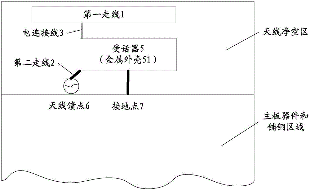
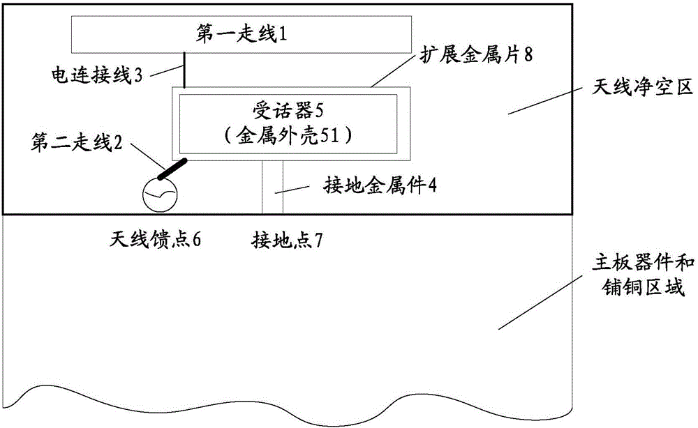
[0027] This embodiment provides an antenna, which includes: an antenna body and a radiator; the antenna body includes a first trace arranged on a printed circuit board, the radiator includes a metal shell of a receiver, and the metal shell is grounded; the first trace passes through an electrical The connection wire is connected to the metal shell of the receiver, and the metal shell of the receiver is connected to the antenna feed point through the second wiring provided on the printed circuit board.

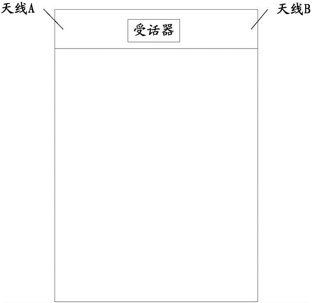
[0028] Specifically, such as figure 1 As shown, the current traditional receiver is generally set in the upper middle position of the terminal, and the receiver is generally made of metal material or is generally equipped with metal parts, such as a metal shell, a metal base, etc.; therefore, in order to prevent the receiver from affecting the antenna The performance of the general antenna is to avoid the receiver setting, such as figure 1 As shown, the antenna A and the anten...

Embodiment 2

[0034] This embodiment provides a carrier radio frequency circuit, including: a radio frequency transceiver, a first circuit network and the antenna of Embodiment 1, the antenna is the first antenna, and the first antenna is electrically connected to the radio frequency transceiver through the first circuit network to form The first transceiving path; the first transceiving path is used for receiving and transmitting the carrier in the first frequency band.

[0035] Specifically, as users' demands on bandwidth resources increase, bandwidth resources are usually increased by way of carrier aggregation. For example, the main solution to realize carrier aggregation of FDD-LTE (Frequency Division Duplexing-Long Term Evolution, Time Division Duplexing-Long Term Evolution) in China is to use higher-cost quadplexers, and the insertion loss of quadplexers is relatively The insertion loss of the duplexer is relatively large, and the PA (Power Amplifier, power amplifier) ​​needs to outp...

Embodiment 3

[0046] This embodiment provides a carrier aggregation method for a terminal including at least a first antenna and a second antenna. The terminal transmits and receives the first carrier frequency carrier to be aggregated through the first antenna; the terminal transmits and receives the second carrier frequency to be aggregated through the second antenna. carrier frequency carrier.

[0047] Specifically, in the carrier aggregation method provided in this embodiment, the first frequency band carrier and the second frequency band carrier to be aggregated are separately sent and received through the first antenna and the second antenna, wherein the first antenna and the radio frequency transceiver form a The first transceiver channel for carrier transmission of the first frequency band; the second transceiver channel for carrier transmission of the second frequency band is formed between the second antenna and the radio frequency transceiver, and the second transceiver channel is...


PUM


Abstract

The embodiment of the invention provides an antenna, a carrier radio frequency circuit, a terminal and a carrier aggregation method. The antenna comprises an antenna body and a radiation body, wherein the antenna body comprises a first wire arranged on a printed circuit board, the radiation body comprises a metal shell of a receiver, and the metal shell of the receiver is grounded; and the first wire is connected with the metal shell of the receiver through an electric connecting wire, and the metal shell of the receiver is connected to an antenna feed point through a second wire arranged on the printed circuit board. According to the invention, the metal shell of the receiver in the terminal is used as the antenna radiation body of the antenna, and an additional antenna radiation body is not required to be arranged, so that setting of the antenna is well realized by effectively utilizing the metal shell of the receiver of the terminal. In addition, the space of an area in which the receiver in the terminal is sufficiently utilized, and the utilization rate of the terminal space is improved.

Description

technical field [0001] The present invention relates to the communication field, in particular to an antenna, a carrier radio frequency circuit, a terminal and a carrier aggregation method. Background technique [0002] With the rapid growth of communication service data and the continuous improvement of users' demand for network resources, the broadband network of mobile communication needs to continuously evolve; in the prior art, CA (Carrier Aggregation, Carrier Aggregation) is generally used to realize the communication bandwidth. Expand to improve the service processing efficiency of the mobile communication network. When implementing carrier aggregation, it is often necessary to increase the number of terminal antennas. However, with the increasing number of mobile phones with full metal back covers, the design of antennas is becoming more and more difficult, and there are strict requirements on the number of antennas. It is impossible to stack many antennas like the ...

Claims


Application Information

Patent Timeline
IPC IPC(8): H01Q1/36H01Q1/38H01Q1/44H04B1/00H04B1/401
CPCH01Q1/36H01Q1/38H01Q1/44H04B1/0057H04B1/006H04B1/0064H04B1/401H04B1/00H04M1/02
Inventor 王伟
Owner YULONG COMPUTER TELECOMM SCI (SHENZHEN) CO LTD
Why Eureka
Try Eureka