Self-sealed wire pulley of power transmission line

A transmission line and self-sealing technology, which is applied in the direction of overhead lines/cable equipment, etc., can solve the problems of aging and poor sealing effects of components, and achieve the effect of improving the safety factor of operations, improving work efficiency, and improving the anti-off rate

Active Publication Date: 2016-12-21
NANYANG POWER SUPPLY COMPANY OF STATE GRID HENAN ELECTRIC POWER +1
View PDF8 Cites 8 Cited by
  • Summary
  • Abstract
  • Description
  • Claims
  • Application Information

AI Technical Summary

Problems solved by technology

[0006] In view of this, the object of the present invention is to address the deficiencies of the prior art and provide a self-sealing wire block for power transmission lines, which greatly improves the anti-off rate of the wire block through the mutual cooperation between the pull rod, the spring, and the limit pin. To improve work efficiency and improve work safety factor, the pull rod and spring can be quickly replaced after removing the limit pin, which solves the problem of poor sealing effect of aging components after long-term use

Method used


Image

  • Self-sealed wire pulley of power transmission line
  • Self-sealed wire pulley of power transmission line
  • Self-sealed wire pulley of power transmission line

Examples


Embodiment 1

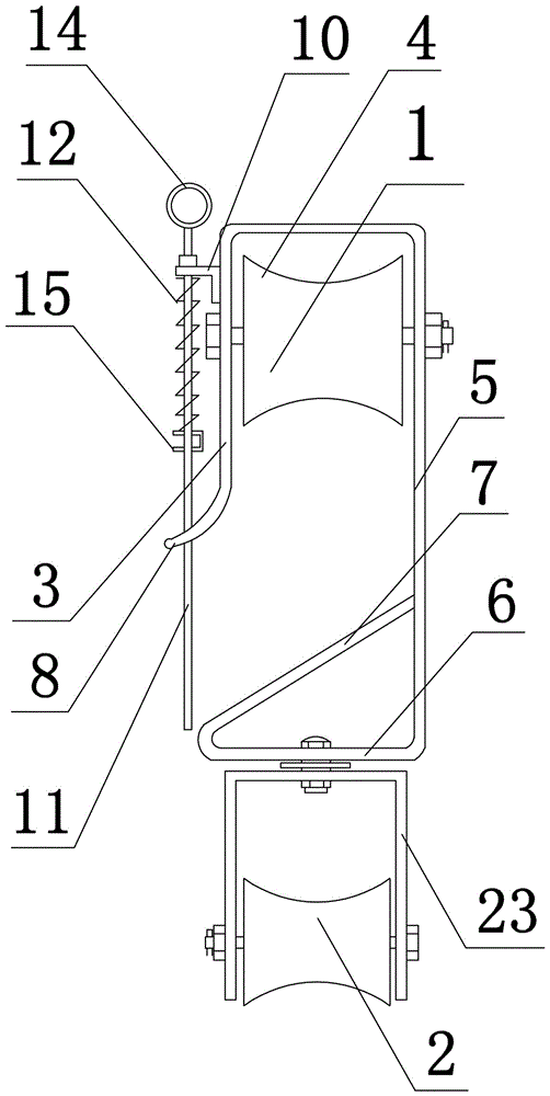
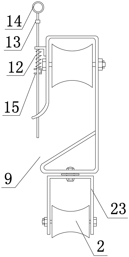
[0028] Such as figure 1 and figure 2 As shown, the present invention comprises a tackle body and a self-sealing device. The tackle body includes a hook and a base 23. A wire pulley 1 is installed in the hook, and a transfer pulley 2 is installed in the base. The hook includes a vertical plate-3 and a horizontal plate-connected in sequence 4, vertical plate two 5, horizontal plate two 6 and inclined plate 7, the length of vertical plate one 3 is less than the length of vertical plate two 5, vertical plate one 3 lower ends are provided with arc plate 8, arc plate 8 and The gap between the horizontal plate two 6 is the opening 9 of the hook, and the vertical plate one 3 outsides are provided with a spacer plate 10, and the spacer plate 10 offers a vertical through hole; the self-sealing device includes a pull bar 11, a spring 12 and Pull rod limit block 13, pull ring 14 is set on the top of pull rod 11, limit pin 15 is set on pull rod 11, spring 12 is sleeved on the outer surfa...

Embodiment 2

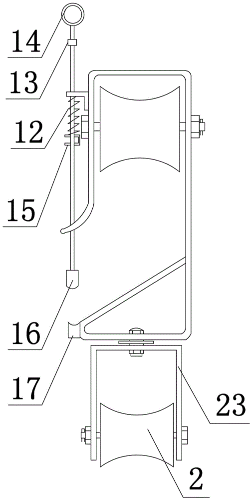
[0031] The structure of this embodiment is basically the same as that of Embodiment 1, the difference is: as image 3As shown, a magnet one 17 is arranged between the inclined plate 7 and the horizontal plate two 6, and the lower end of the pull rod 11 is fixedly connected to the magnet two 16 which is attracted to each other by the magnet one 16. The lower end of the magnet one 17 is an arc groove structure, and the upper end of the magnet two 16 is It is an arc-shaped convex structure cooperating with magnet one 17. The suction force F1 when magnet one 17 and magnet two 16 are in contact is greater than the maximum elastic force F2 of spring 12, and the suction force F1 when magnet one 17 and magnet two 16 are in contact is smaller than this. Invent the self-weight G of the whole.

[0032] In this embodiment, the mutual attraction between the magnet one 17 set between the inclined plate 7 and the horizontal plate two 6 and the magnet two 16 set at the lower end of the pull r...

Embodiment 3

[0034] The structure of this embodiment is basically the same as that of Embodiment 1, the difference is: as Figure 4 As shown, the transmission pulley 2 includes a transmission pulley one 18 and a transmission pulley two 19 arranged up and down, the two side edges of the transmission pulley one 18 are provided with a tooth one 20, and the two side edges of the transmission pulley two 19 are provided with teeth matched with the tooth one 20. Two 21.

[0035] In this implementation, the lower end of the first transmission pulley 18 is geared with the upper end of the second transmission pulley 19. Through the principle of synchronous rotation of the double pulleys, the traction rope that pulls the transmission pulley 2 is clamped between the first transmission pulley 18 and the second transmission pulley 19 during use. In between, the side slipping problem of the traction rope can be effectively prevented, that is, the first transmission pulley 18 and the second transmission p...


PUM


Abstract

The invention discloses a self-sealed wire pulley of a power transmission line. The self-sealed wire pulley comprises a pulley body and a self-sealed device, wherein the pulley body comprises a hook and a base, the hook comprises a first vertical plate, a first horizontal plate, a second vertical plate, a second horizontal plate and an inclination plate which are sequentially connected, the length of the first vertical plate is smaller than the length of the second vertical plate, an arc plate is arranged at a lower end of the first vertical plate, a limiting plate is arranged at an outer side of the first vertical plate, a through hole is formed in the limiting plate in a vertical direction, the self-sealed device comprises a pull rod, a spring and a pull rod limiting block, a pull ring is arranged at a top end of the pull rod, a limiting pin is arranged on the pull rod, and the spring sleeves an outer surface of the pull rod. Through matching among the pull rod, the spring and the limiting pin, the disconnection preventing rate of the wire pulley is greatly improved, the purposes of improving the working efficiency and improving the operation safety coefficient are achieved, the pull rod and the spring can be rapidly replaced after the limiting pin is removed, and the problem of poor sealing effect due to part aging after long-term usage is solved.

Description

technical field [0001] The technical field of the transmission line maintenance device of the present invention, in particular, relates to a transmission line self-sealing wire pulley. Background technique [0002] At present, most of the overhead transmission lines in my country are located in the wilderness and suburbs. The electrical part of the line is affected by electromechanical, climate and environmental pollution. Ground wires, insulators, and fittings are prone to defects such as broken strands, insulator zero value or self-explosion, and fittings corrosion. . With the development of our country's economy, all sectors of the national economy, including people's daily electricity consumption, have put forward the requirements for continuous and reliable power supply. In order to prevent power supply enterprises from stopping power supply due to equipment experiments, maintenance and processing equipment defects, causing losses to industrial and agricultural producti...

Claims


Application Information

Patent Timeline
Patent Type & Authority Applications(China)
IPC IPC(8): H02G1/02
CPCH02G1/02
Inventor 王坤王峰庄严李成彦李宴都王欢马洪举段君丽全晓杨子垲陈柳宁张汶卓马建波张继凯尹应军胡新泉王海涛赵炎辉张义强鲁清海耿军马超白松林符惠聪姚军张超
Owner NANYANG POWER SUPPLY COMPANY OF STATE GRID HENAN ELECTRIC POWER
Why Eureka
Try Eureka