
Car network-coupled power flow calculation method for metro power supply system

A power flow and power supply system technology, applied in the field of simulation, can solve the problem of low accuracy of calculation results, achieve fast calculation speed, good real-time performance, and improve the calculation speed

Active Publication Date: 2016-12-21
CHENGDU YUNDA TECH CO LTD
View PDF5 Cites 26 Cited by
  • Summary
  • Abstract
  • Description
  • Claims
  • Application Information

AI Technical Summary

Problems solved by technology

[0004] What the present invention aims to solve is the problem that the accuracy of calculation results is not high due to the calculation method of separate iteration of AC and DC for the simulation of subway OCC ESC

Method used


Image

  • Car network-coupled power flow calculation method for metro power supply system
  • Car network-coupled power flow calculation method for metro power supply system
  • Car network-coupled power flow calculation method for metro power supply system

Examples


Embodiment

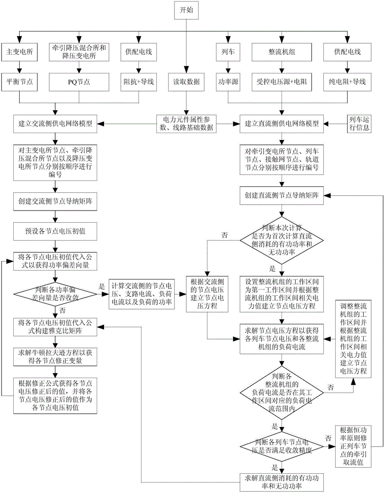
[0028] An embodiment of the present invention provides a power flow calculation method for a subway power supply system coupled with a vehicle network, including:

[0029] Step S10, based on the coupling relationship between the power supply system and the train operation, simulate the attribute parameters of the equivalent AC and DC side power components;

[0030] Step S11, establishing a DC side power supply network model and an AC side power supply network model according to the AC and DC side power component attribute parameters, line basic data and train operation information;

[0031] Step S12, according to the DC-side power supply network model and the AC-side power supply network model, iteratively calculate the DC-side power flow value and the AC-side power flow value.

[0032] figure 1 It is a schematic flow chart of a power flow calculation method for a train-network coupled subway power supply system according to an embodiment of the present invention. Specifical...


PUM


Abstract

The invention discloses a car network-coupled power flow calculation method for a metro power supply system. The method comprises the steps of (S10) simulating equivalent AC / DC side electric power component attribute parameters on the basis of a coupling relationship between a power supply system and train operation; (S11) building a DC side power supply network model and an AC side power supply network model according to the AC / DC side electric power component attribute parameters, basic data of lines and train operation information; and (S12) carrying out cross iterative calculation on a DC side power flow value and an AC side power flow value according to the DC side power supply network model and the AC side power supply network model. By the car network-coupled power flow calculation method for the metro power supply system disclosed by the invention, the calculation accuracy of the power flow values can be effectively improved through cross iterative calculation of the DC side power supply network model and the AC side power supply network model.

Description

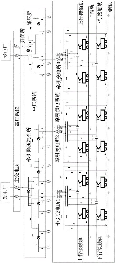
technical field [0001] The invention relates to the technical field of simulation, in particular to a power flow calculation method for a subway power supply system coupled with a vehicle network. Background technique [0002] The subway power supply system is the source of power for urban rail transit operations. It is mainly responsible for the transmission, conversion and supply of electric energy, powering electric trains and providing power for power lighting for subway stations, sections, depots, control centers and other buildings. According to different system functions, the subway power supply system is divided into: external power supply, main substation or power switch station, traction substation, and power substation, mainly composed of high-voltage power supply system, traction power supply system, and power lighting power supply system. Partial composition. Among them, the external power supply is the direct power supply spring of the main substation or the p...

Claims


Application Information

Patent Timeline
Patent Type & Authority Applications(China)
IPC IPC(8): H02J3/06
CPCH02J3/06H02J2203/20
Inventor 黄成周李跃宗张家华
Owner CHENGDU YUNDA TECH CO LTD
Learn More