Optical module

An optical module and laser technology, applied in the field of optical communication, can solve problems such as the jitter of the optical eye pattern, and achieve the effects of shortening the duration of high-level, reducing the duty cycle, and prolonging the duration of low-level

Inactive Publication Date: 2016-12-21
HISENSE BROADBAND MULTIMEDIA TECH
View PDF3 Cites 9 Cited by
  • Summary
  • Abstract
  • Description
  • Claims
  • Application Information

AI Technical Summary

Problems solved by technology

Since the jitter of the optical eye diagram is associated with the internal resistance and capacitance of the optical module, forcibly modifying the internal resistance and capacitance of the optical module will cause the jitter of the optical eye diagram in the optical module to increase

Method used


Image

  • Optical module
  • Optical module
  • Optical module

Examples


Embodiment Construction

[0025] In order to enable those skilled in the art to better understand the technical solutions in the present invention, the technical solutions in the embodiments of the present invention will be clearly and completely described below in conjunction with the drawings in the embodiments of the present invention. Obviously, the described The embodiments are only some of the embodiments of the present invention, not all of them. Based on the embodiments of the present invention, all other embodiments obtained by persons of ordinary skill in the art without creative efforts shall fall within the protection scope of the present invention.

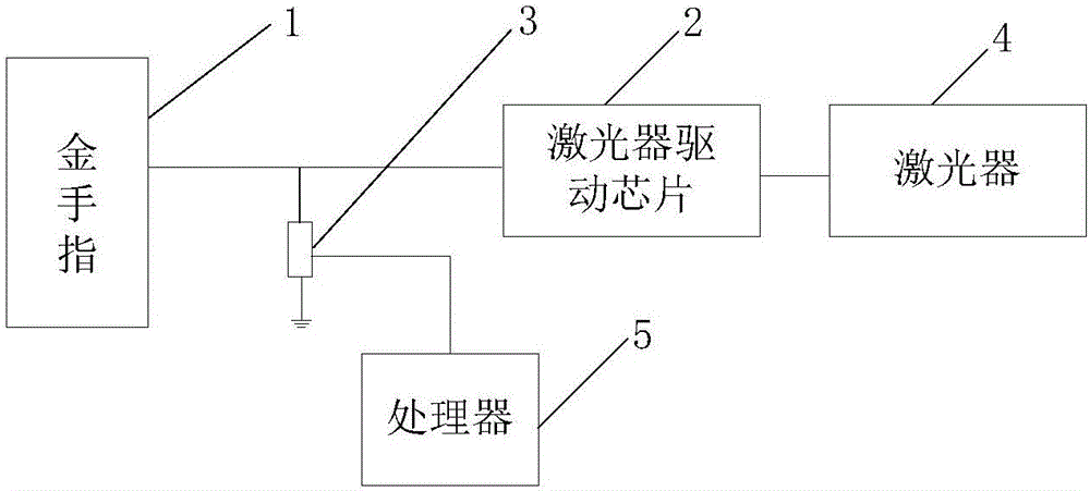
[0026] see image 3 , in an optical module provided in an embodiment of the present invention, it includes a golden finger 1, a laser driver chip 2, a variable resistor 3, a laser 4 and a processor 5.

[0027] The gold finger 1 is provided with a signal interface for outputting current signals, the external host computer inputs the current si...


PUM


Abstract

The embodiment of the invention discloses an optical module, comprising a gold finger, a laser drive chip, a laser and a variable resistor. The gold finger is equipped with a signal interface and is used for outputting a current signal. The laser drive chip is equipped with a signal receiving end and a drive signal output end. The signal receiving end is connected with the signal interface. The drive signal output end is connected with the laser and is used for driving the laser to transmit an optical signal. The signal receiving end and one end of the variable resistor are connected with the signal interface. The other end of the variable resistor is grounded. When the duty cycle of the current single is overhigh, the variable resistor is adjusted, the resistance value of the variable resistor is reduced, the current input to the laser drive chip is reduced, a voltage signal amplitude is reduced, a high level part in the voltage signal is pulled down, the duty cycle is reduced, and an intersection in an optical eye diagram moves towards the middle position of the optical eye diagram. When the duty cycle of the input electric signal is changed, other resistance and capacitance in the optical module are not modified, so that jitter of the optical eye diagram is not influenced.

Description

technical field [0001] Embodiments of the present invention relate to the field of optical communications, and in particular, to an optical module. Background technique [0002] In the field of optical communication, an optical module is a device that realizes photoelectric conversion. The optical module transmits the converted optical signal to the receiving end through the optical fiber. If the quality of the optical signal transmitted by the optical module is poor, the probability of bit errors or data loss at the receiving end will increase. Therefore, in actual engineering, in order to confirm the quality of the optical signal emitted by the optical module, the quality of the optical signal will be tested. [0003] The current optical signal detection method usually uses a bit error detector to simulate the actual application environment, converts the electrical signal generated by the bit error detector into an optical signal through an optical module, and inputs the...

Claims


Application Information

Patent Timeline
Patent Type & Authority Applications(China)
IPC IPC(8): H04B10/073H04B10/27
CPCH04B10/0731H04B10/27
Inventor 段耀宇
Owner HISENSE BROADBAND MULTIMEDIA TECH
Why Eureka
Try Eureka