
Diagnosis routing method and system based on independent gateway

An independent network and routing technology, applied in the transmission system, digital transmission system, data exchange network, etc., can solve the problems of high detection error rate, increased diagnostic CAN load, exceeding the diagnostic CAN load rate, etc., to meet the test requirements, increase Real-time and safety, effect of load reduction

Inactive Publication Date: 2016-12-21
ZHEJIANG GEELY HLDG GRP CO LTD +1
View PDF7 Cites 10 Cited by
  • Summary
  • Abstract
  • Description
  • Claims
  • Application Information

AI Technical Summary

Problems solved by technology

[0005] However, this method of copying the entire CAN channel information to the diagnostic route will undoubtedly greatly increase the load of the diagnostic CAN, resulting in actual detection exceeding the diagnostic CAN load rate and frame loss, and the detection error rate is high.

Method used


Image

  • Diagnosis routing method and system based on independent gateway
  • Diagnosis routing method and system based on independent gateway
  • Diagnosis routing method and system based on independent gateway

Examples


Embodiment 1

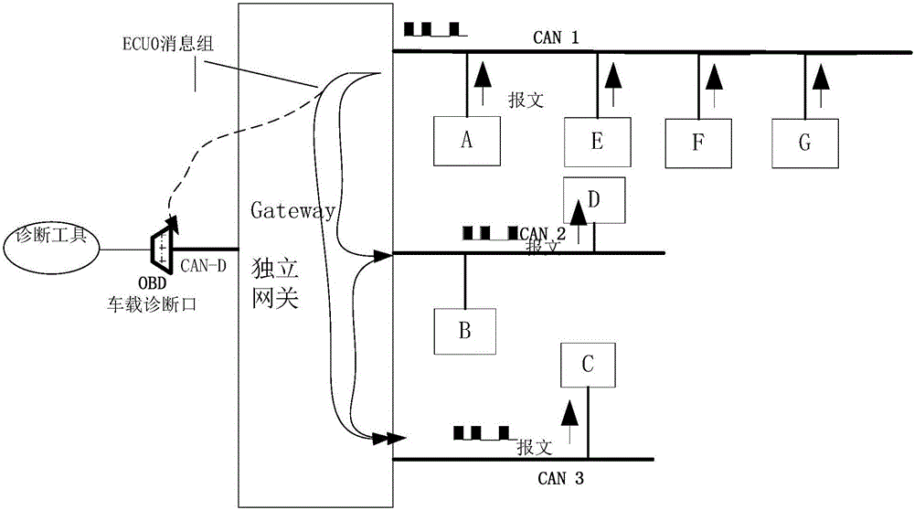
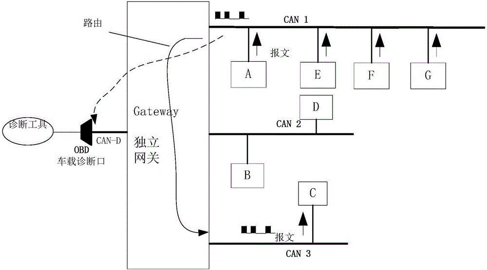
[0031] figure 2 is a schematic diagram of the mapping routing method in the traditional diagnostic routing method. like figure 2 As shown, the gateway is connected to 4 networks: CAN1, CAN2, CAN3 and 1 diagnostic CAN (CAN-D). The diagnostic tool is connected to the gateway diagnostic network CAN-D through OBD (on-board diagnostic port), among which CAN1 is There are 4 nodes, respectively: node A, node E, node F, and node G. The load rate of the CAN1 network segment is 40% during normal operation; All messages of node F, node G are all mapped (that is, "copied") to CAN-D OBD, and the load rate on CAN-D OBD will reach 40% at this time.

[0032] Therefore, in the traditional diagnostic routing method, according to the actual diagnostic test requirements, due to the constraints of the CAN network segment load rate, in the case of multiple IDs in the same network or different networks, the actual detection may exceed the diagnostic CAN load rate. and dropped frames.

[0033] ...

Embodiment 2

[0096] This embodiment describes a diagnostic routing system based on an independent gateway, which may generally include: an independent gateway; multiple CAN lines connected to the independent gateway, and the multiple CAN lines include a diagnostic CAN and at least two CAN network; a diagnostic tool, the diagnostic tool has an on-board diagnostic port, and the on-board diagnostic port is connected to the diagnostic CAN; and a node selection control unit, which selects a specific node in the at least two CAN networks according to user input. The node serves as a diagnosis node, and maps the message sent by the diagnosis node to the diagnosis CAN where the on-board diagnostic port is located.

[0097] There are several nodes on the at least two CAN networks, and the diagnostic routing method selects at least one node among the several nodes as a node that needs to be observed and tracked, and the at least one node is selected during the diagnostic routing process. The message...


PUM


Abstract

The invention provides a diagnosis routing method and system based on an independent gateway. The method comprises: the independent gateway, multiple CAN lines, and a diagnosis tool; the multiple CAN lines are connected with the independent gateway, and comprise a diagnosis CAN and at least two CAN networks; the diagnosis tool is provided with a vehicular diagnosis port; the vehicular diagnosis port is connected with the diagnosis CAN, wherein the diagnosis routing method comprises the following steps of: selecting a specific node in the at least two CAN networks as a diagnosis node, and mapping a message sent by the diagnosis node to the diagnosis CAN, where the vehicular diagnosis port is. By means of the diagnosis routing method and system disclosed by the invention, an information source and an information receiver can be clearly judged; furthermore, load of a diagnosis network CAN-D can be reduced; the monitoring real-time performance and the security are improved; and more fine testing requests can be satisfied.

Description

technical field [0001] The invention relates to a diagnostic routing method and system based on an independent gateway. Background technique [0002] With the rapid development of automobile technology, the demand for vehicle electrical functions is increasing, and there are more and more signal interactions. Basically, the existing foreign and domestic models, CAN network communication has achieved standard configuration, and basically all electrical nodes of the vehicle are connected to the whole vehicle. Vehicle CAN network to realize high-speed signal transmission. [0003] Therefore, more and more attention is paid to the development of the signal router gateway as a vehicle CAN network, and the verification of the gateway, especially the signal test, has become an important link in the development and verification process of the vehicle. [0004] The functional test for the gateway mainly includes routing test and diagnostic function test for each CAN channel, and the...

Claims


Application Information

Patent Timeline
Patent Type & Authority Applications(China)
IPC IPC(8): H04L12/26H04L29/08
CPCH04L43/00H04L43/08H04L67/12
Inventor 景凯项苠
Owner ZHEJIANG GEELY HLDG GRP CO LTD
Learn More