A handle-type lavage device and a fiberoptic bronchoscope using the lavage device
A fiberoptic bronchoscope and handle technology, applied in the field of medical devices, can solve the problems of occupying a large amount of human resources and hidden dangers, and achieve the effects of improving safety, reducing investment costs and being convenient to use.
- Summary
- Abstract
- Description
- Claims
- Application Information
AI Technical Summary
Problems solved by technology
Method used
Image
Examples
Embodiment 1
[0036] Embodiment 1, as shown in the figure,
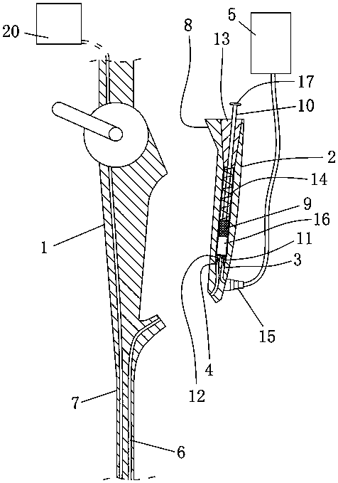
[0037]A handle-type lavage device, comprising a handle 2, the handle 2 is connected to the handle 1 of the fiberoptic bronchoscope, the handle 2 is provided with a suction device, and the liquid suction device includes a liquid inlet 3 and a liquid outlet 4. The liquid inlet 3 is used to communicate with the lavage fluid collection device 5, the liquid outlet 4 is used to communicate with the lavage hole 6 of the fiberoptic bronchoscope catheter 7, and the liquid suction device is used to extract The lavage fluid collects the lavage fluid in the device 5 and presses it into the lavage hole 6 of the catheter 7 .
[0038] In the handle 1 type lavage device of the present application, the handle 2 is matched with the handle 1 in the traditional fibrous bronchus structure. Since the handle 2 is provided with a pumping device, the lavage fluid can be collected by the pumping device during use by the doctor. The lavage fluid in the dev...
Embodiment 2
[0042] Embodiment 2, as shown in the figure:
[0043] In the handle 1 type irrigation device structure as described in Embodiment 1, the liquid pumping device includes a liquid cylinder 16 and a piston 9 matched with the liquid cylinder 16, and a push rod 10 is arranged on the piston 9, The bottom of the hydraulic cylinder 16 is provided with a first one-way valve 11 and a second one-way valve 12, the outlet of the first one-way valve 11 is the liquid outlet 4, and the outlet of the second one-way valve 12 is The inlet is the liquid inlet 3.
[0044] When in use, when the push rod 10 pushes the piston 9 to move upward in the liquid cylinder 16, under the action of negative pressure, the first one-way valve 11 is closed, the second one-way valve 12 is opened, and the lavage fluid is collected by the lavage fluid. The device 5 enters the liquid cylinder 16 through the second one-way valve 12, and when the piston 9 moves toward the bottom of the liquid cylinder 16, under the act...
Embodiment 3
[0052] Embodiment 3, as shown in the figure:
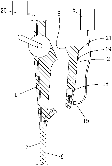
[0053] In the structure of the handle 1 type irrigation device as described in Embodiment 1, the pumping device is a pumping device, and the pumping device includes a liquid pump 18, and the inlet of the liquid pump 18 is the liquid inlet 3. The outlet of the liquid pump 18 is the liquid outlet 4 .
[0054] Further preferably, the liquid pump 18 is connected with a first switch 19 for controlling its start and stop. It is convenient to control the start and stop of the liquid pump 18.
[0055] Further preferably, the first switch 19 is arranged on the handle 2 . When the doctor uses the fiberoptic bronchoscope, one hand grasps the handle 2, so the first switch 19 is arranged on the handle 2, and in the normal operation state, the doctor can also control the first The switch 19 further controls the start and stop of the pumping device, which further facilitates the doctor's use.
[0056] Preferably, the handle 2 is further prov...
PUM
 Abstract
Description
Claims
Application Information
 - R&D
- Intellectual Property
- Life Sciences
- Materials
- Tech Scout
- Unparalleled Data Quality
- Higher Quality Content
- 60% Fewer Hallucinations
Browse by: Latest US Patents, China's latest patents, Technical Efficacy Thesaurus, Application Domain, Technology Topic, Popular Technical Reports.
© 2025 PatSnap. All rights reserved.Legal|Privacy policy|Modern Slavery Act Transparency Statement|Sitemap|About US| Contact US: help@patsnap.com


