AI technical title is built by PatSnap AI team. It summarizes the technical point description of the patent document.
A technology of crushing device and bottom plate, which is applied in the direction of grain processing, etc., can solve the problems of difficult fixing of large ores, easy splashing of small stones and hurting people, etc., and achieve the effect of preventing the movement of ore.
Active Publication Date: 2017-01-04
ZUNYI LUXIN MACHINERY CO LTD
View PDF5 Cites 2 Cited by
Summary
Abstract
Description
Claims
Application Information
AI Technical Summary
This helps you quickly interpret patents by identifying the three key elements:
Problems solved by technology
Method used
Benefits of technology
Problems solved by technology
[0006] The invention provides a crushing device for the technical problems that small stones are easy to splash and hurt people, and large ores are difficult to fix during the preliminary crushing process.
Method used
Image
Click on the blue label to locate the original text in one second.
Reading with bidirectional positioning of images and text.
Examples
Embodiment 1
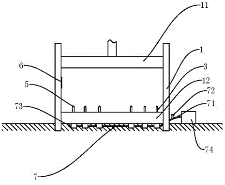
[0030] Basic as attached figure 1 Shown: Shredder, consisting of:
[0031] Frame, the frame is fixedly installed on the ground, the frame is surrounded by baffles, and the inner side of the baffle is provided with a spongecushion;
[0032] Press plate, the frame is provided with a slide rail for the press plate to slide up and down, and a hydraulic press is fixed above the press plate, and the hydraulic press drives the press plate to rise or fall;
[0033] The bottom plate, the bottom plate is fixed on the ground, the bottom plate is fixedly connected with the frame, the bottom plate is located directly under the pressure plate, and the bottom plate is provided with connection holes;
[0034] Locating pin, the locating pin is located in the connection hole, the locating pin is slidingly connected with the bottom plate, the upper part of the locating pin is provided with a spherical crown, and the crown is wrapped with a rubber layer;
[0035] Cylinder, the cylinder is buri...
Embodiment 2
[0040] Compared with Example 1, the only difference is that there is a powder leakage hole on the bottom plate, and the powder leakage hole and the connecting hole are arranged at intervals, and a collection bin is arranged under the powder leakage hole, and the collection bin is buried under the bottom plate, and the inner wall of the collection bin A rubber layer is bonded, a screw is nailed on the rubber layer, a hair ball is tied with a rope on the screw, and the hair ball can swing freely on the rubber layer. During the initial crushing process, the frame and the ground will vibrate slightly, which will cause the hair ball to swing. During the swing process, the rubber layer will be charged, so that the rubber layer can absorb the powder falling from the powder leakage hole. of fine dust.
Embodiment 3
[0042] Compared with Embodiment 1, the only difference is that the infrared sensor is replaced by a pressure sensor. The pressure sensor is located on the movement track of the pressing plate, and the pressure sensor is fixed on the frame. The pressure sensor takes its own pressure as the basis for judgment, has a simple structure, is convenient to install, and is accurate in judgment.
PUM
Abstract
The invention belongs to the field of building equipment and particularly discloses a crushing device. The crushing device comprises a rack, a pressing plate, a bottom plate, positioning pins and air cylinders, wherein a formwork is fixedly mounted on the ground and baffles are arranged at the periphery of the rack; the pressing plate is in sliding connection with the rack; a hydraulic cylinder is fixedly arranged above the pressing plate; the hydraulic cylinder drives the pressing plate to ascend or descend; the bottom plate is fixed on the ground, is fixedly connected with the rack, is located just below the pressing plate, and is provided with connecting holes; the positioning pins are located in the connecting holes; the positioning pins are in sliding connection with the bottom plate; a sphere-crown-shaped crown head is arranged at the upper part of each positioning pin; the air cylinders are buried below the bottom plate; each positioning pin is connected with the corresponding air cylinder; the air cylinders are respectively used for driving the positioning pins to stretch out or retract back; connecting pipes, which are communicated with one another, are arranged among all the air cylinders; the connecting pipes are provided with pressure leaking pipes. Aiming at the technical problems that small stone blocks are easily splashed to injure people and large ores are difficult to fix in a primary crushing process, the invention provides the crushing device.
Description
technical field [0001] The invention relates to the field of construction equipment, in particular to a crushing device. Background technique [0002] Crusher is widely used in fine crushing and coarse grinding of metal and non-metal ores, cement, refractory materials and various metallurgical slags. [0003] Ordinary crushers will directly perform crushing operations in the crushing cavity. However, when encountering some large ores, the impact crushing method is usually used for preliminary crushing, and the large ore is initially crushed into several smaller ores that can enter the crushing cavity, and then the polar crushing operation is performed with a crusher. [0004] In the actual processing process, this preliminary crushing operation is actually very troublesome and dangerous. During the initial crushing process, small stones often splash and hurt people. And in the process of primary crushing, large ore is also easy to move, which increases the difficulty of p...
Claims
Application Information
Patent Timeline
Application Date:The date an application was filed.
Publication Date:The date a patent or application was officially published.
First Publication Date:The earliest publication date of a patent with the same application number.
Issue Date:Publication date of the patent grant document.
PCT Entry Date:The Entry date of PCT National Phase.
Estimated Expiry Date:The statutory expiry date of a patent right according to the Patent Law, and it is the longest term of protection that the patent right can achieve without the termination of the patent right due to other reasons(Term extension factor has been taken into account ).
Invalid Date:Actual expiry date is based on effective date or publication date of legal transaction data of invalid patent.

