Metal foil rolling device

A metal foil, consistent technology, applied in the direction of metal rolling, etc., can solve the problems of difficult adjustment and uneven rolling thickness

Inactive Publication Date: 2017-01-04
JIANGSU YOUZHA MACHINE CO LTD
View PDF9 Cites 5 Cited by
  • Summary
  • Abstract
  • Description
  • Claims
  • Application Information

AI Technical Summary

Problems solved by technology

[0002] Metal foil is a thin metal sheet extended from metal. It is generally prepared by rolling or electrolysis in rolling equipment. Although the cost of electrolytic preparation is low, rolling production has good ductility and other characteristics. For example, copper foil In production, due to the fact that there are fewer manufacturers of rolled copper foil, and the technology is also in the hands of some manufacturers, today's equipment preparation has defects such as difficult adjustment and uneven rolling thickness, so the customer does not affect the performance of the product. Under the current situation, replacing calendered copper foil with electrolytic copper foil has become the mainstream solution
However, due to the current physical characteristics of the copper foil itself that will affect the etching factors, in thinner or thinner products, and in addition to high-frequency products due to telecommunications considerations, the importance of rolled copper foil will increase again, so it is necessary. A device with convenient and quick adjustment and high precision

Method used


Image

  • Metal foil rolling device
  • Metal foil rolling device
  • Metal foil rolling device

Examples


Embodiment Construction

[0020] The following will clearly and completely describe the technical solutions in the embodiments of the present invention with reference to the accompanying drawings in the embodiments of the present invention. Obviously, the described embodiments are only some, not all, embodiments of the present invention. Based on the embodiments of the present invention, all other embodiments obtained by persons of ordinary skill in the art without creative efforts fall within the protection scope of the present invention.

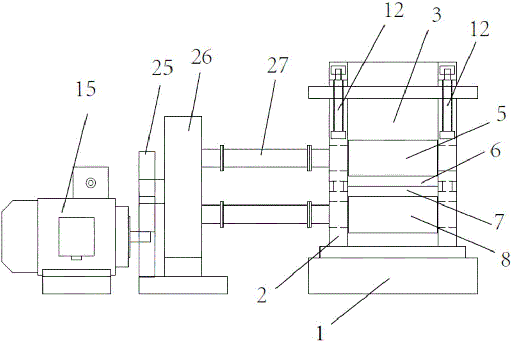
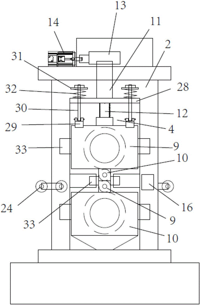
[0021] refer to Figure 1 to Figure 3 As shown, a metal foil rolling device includes a base 1, two support plates 2 are symmetrically arranged on the base, a rolling space 3 is arranged between the two support plates, and an adjustment opening 4 is arranged on the support plate. The upper power large roller 5, the upper transmission small roller 6, the lower transmission small roller 7 and the lower power large roller 8 are arranged sequentially from top to bottom ...


PUM


Abstract

The invention discloses a metal foil rolling device which comprises a base. Two support plates are symmetrically arranged on the base, a rolling space is formed between the two support plates, adjusting open holes are formed in the support plates, a large upper power roller, a small upper driving roller, a small lower driving roller and a large lower power roller are sequentially arranged in the rolling space from top to bottom, a first bearing seat is arranged at two ends of the large upper power roller and two ends of the large lower power roller respectively, a second bearing seat is arranged at two ends of the small upper driving roller and two ends of the small lower driving roller respectively, the first bearing seats and the second bearing seats are arranged in the adjusting open holes, inner threaded sleeves are further arranged on the support plates above the adjusting open holes, threaded rods are arranged in the inner threaded sleeves, one end of the threaded rod is in abut joint with the corresponding first bearing seat of the large upper power roller, the other end of the threaded rod is connected with a worm wheel, and the worm wheels are connected with a pushing motor through worms. The metal foil rolling device is compact in structure, convenient to adjust and high in production precision.

Description

technical field [0001] The invention relates to the field of metal strip preparation, in particular to a metal foil rolling device. Background technique [0002] Metal foil is a thin metal sheet extended from metal. It is generally prepared by rolling or electrolysis in rolling equipment. Although the cost of electrolytic preparation is low, rolling production has good ductility and other characteristics. For example, copper foil In production, due to the fact that there are fewer manufacturers of rolled copper foil, and the technology is also in the hands of some manufacturers, today’s equipment preparation has defects such as difficult adjustment and uneven rolling thickness, so the customer does not affect the performance of the product. Under the current situation, replacing rolled copper foil with electrolytic copper foil has become the mainstream solution. However, due to the current physical characteristics of the copper foil structure that will affect the etching fa...

Claims


Application Information

Patent Timeline
Patent Type & Authority Applications(China)
IPC IPC(8): B21B1/40
CPCB21B1/40
Inventor 穆开洪帅立国张弛万嵘
Owner JIANGSU YOUZHA MACHINE CO LTD
Why Eureka
Try Eureka