Split roller and process for machining workpiece through split roller

A roll and split technology, applied in the direction of rolls, metal processing equipment, metal rolling, etc., can solve problems such as dimensional tolerances

Active Publication Date: 2017-01-04
SHANDONG HONGMIN ROLLER MOLD
View PDF9 Cites 1 Cited by
  • Summary
  • Abstract
  • Description
  • Claims
  • Application Information

AI Technical Summary

Problems solved by technology

However, due to the requirement of dimensional tolerance for pipe diameter, the relative position of B roller and C roller should form a precise round hole shape, so it is required to turn it with CNC as a whole to ensure the accuracy of use. However, due to B The rollers are passive and will slide relative to the A and C rollers during turning

Method used


Image

  • Split roller and process for machining workpiece through split roller
  • Split roller and process for machining workpiece through split roller
  • Split roller and process for machining workpiece through split roller

Examples


Embodiment Construction

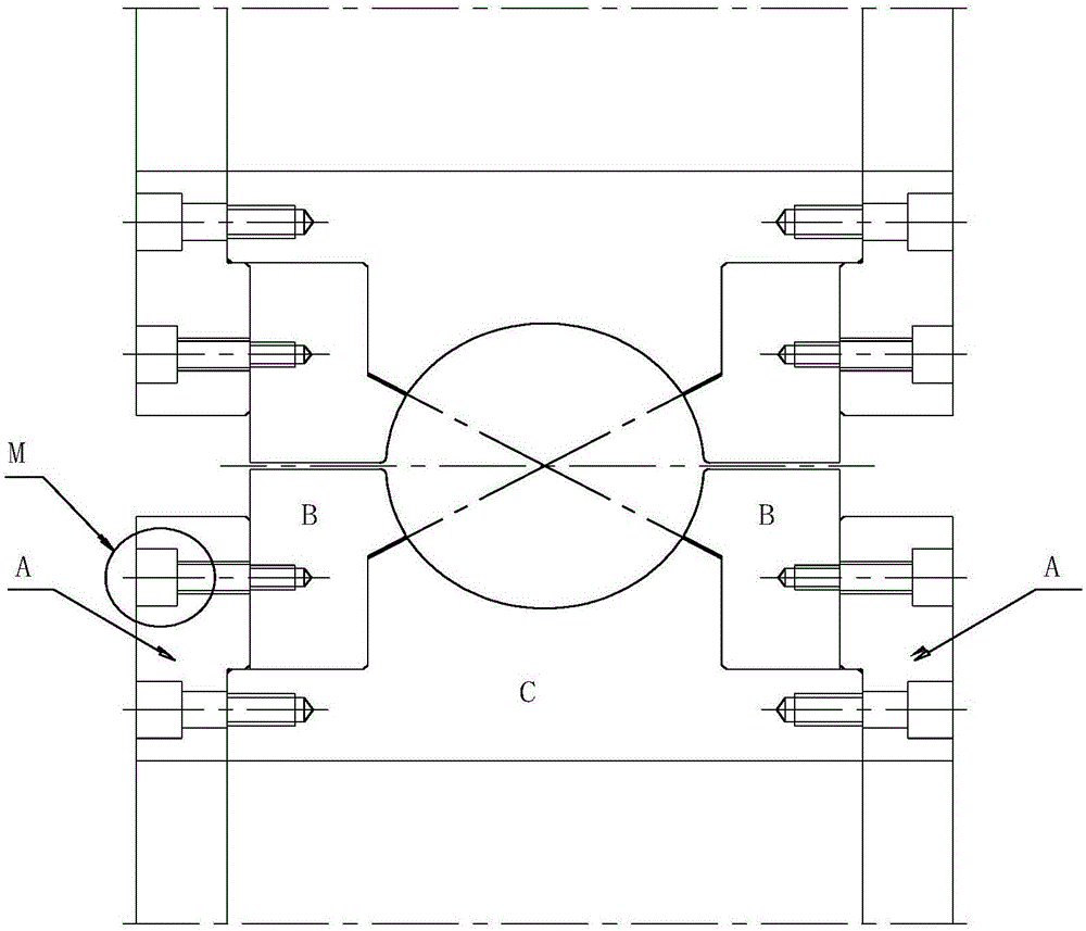
[0031] Such as figure 1 As shown, the device used in the present invention includes two split roll groups arranged symmetrically up and down, and a cylindrical cavity is formed between the two split roll groups, and each split roll group includes a set of coaxially installed The A roll, the B roll and the C roll, the B roll includes two, which are symmetrically arranged on the shoulder 3-3 of the C roll with respect to the center line of the C roll, and the two B rolls are connected to the The combination of the C rollers forms a semicircular working surface. The A rollers include two, which are arranged on the outside of the shoulders of the C rollers relative to the center line of the C rollers and are connected with the C rollers by bolts. The B roll and the A roll are also connected by bolts, so that when the split roll is processed, the A roll, the B roll and the C roll form a whole.

[0032] Further, the non-working surface of the B roller is provided with three screw h...


PUM


Abstract

The invention discloses a split roller and a process for machining a workpiece through the split roller. The split roller comprises roller bodies A, roller bodies B and a roller body C, wherein the roller bodies A, the roller bodies B and the roller body C are a whole set of the disc structure, the roller bodies B are arranged on a shaft shoulder of the roller body C and coaxial with the roller body C, a semicircular cavity is formed after the roller bodies B and the roller body C are combined, the roller bodies A are arranged on the outer side of the shaft shoulder of the roller body C and coaxially connected with the roller body C through bolts, and the roller bodies A and the corresponding roller bodies B are also connected through bolts, so that when the split roller is machined, the roller bodies A, the roller bodies B and the roller body C are integrated.

Description

technical field [0001] The invention discloses a split roll and a process for processing workpieces by using the roll. Background technique [0002] In the design process of the roll, some welded pipes have very high requirements on the surface quality, but in the rolling process, the phenomenon of sticky material scratches caused by the difference in line speed always exists, which requires us to make the roll into a separate structure. Such as figure 1 As shown, the A roller and the C roller are connected together by bolts. At the same time, the inner hole of the C roller has a keyway and the shaft with power rotates at the same time through the key connection, which is equivalent to a whole roller. The B roller is passed through the inner hole and the C roller. The shoulder shafts on the side cooperate with each other and passively rotate under the drive of the strip, which also solves the sticking phenomenon caused by the difference in line speed at the contact point be...

Claims


Application Information

Patent Timeline
Patent Type & Authority Applications(China)
IPC IPC(8): B21B27/02B23P15/00
CPCB21B27/02B21B2267/00B23P15/00
Inventor 梁涛
Owner SHANDONG HONGMIN ROLLER MOLD
Why Eureka
Try Eureka