Dynamic specification-changing moving method for working rollers of cold continuous mill

A technology of dynamically changing specifications and cold tandem mills, applied in the field of rolling control, can solve problems such as broken strips, inability to ensure the control accuracy of the strip edges at the head and tail, and inability to ensure the set position of roll shifting

Active Publication Date: 2017-01-04
ANGANG STEEL CO LTD
View PDF8 Cites 6 Cited by
  • Summary
  • Abstract
  • Description
  • Claims
  • Application Information

AI Technical Summary

Problems solved by technology

The usual method is that the work roll starts to move when the weld seam is 10 meters away from the roll seam of the first stand, which is affected by the work roll movement speed, the change of the entrance strip speed, the rolling speed of each stand, the rolling force of each stand, etc. Due to the influence of various factors, it is impossible to ensure that the work roll has shifted to the set position of the wor

Method used


Image

  • Dynamic specification-changing moving method for working rollers of cold continuous mill
  • Dynamic specification-changing moving method for working rollers of cold continuous mill
  • Dynamic specification-changing moving method for working rollers of cold continuous mill

Examples


Embodiment Construction

[0080] The present invention will be described in further detail below in conjunction with the accompanying drawings.

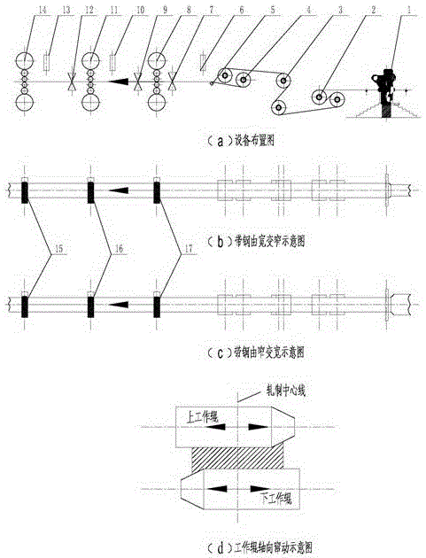
[0081] The present invention is suitable for single-ended tapered work roll traverse mills, see figure 1 . The first frame 8, the second frame 11, and the third frame 14 have the function of working lateral movement. The equipment includes entrance convexity meter 1, 5#S roller 2, deviation correction roller 3, 6#S roller 4, steering roller 5, the first rack entrance laser speed gauge 6, the first rack entrance thickness gauge 7, the first Thickness gauge 9 at the exit of the rack, laser speed gauge 10 at the entrance of the second rack, thickness gauge 12 at the exit of the second rack, and laser speed gauge 13 at the entrance of the third rack.

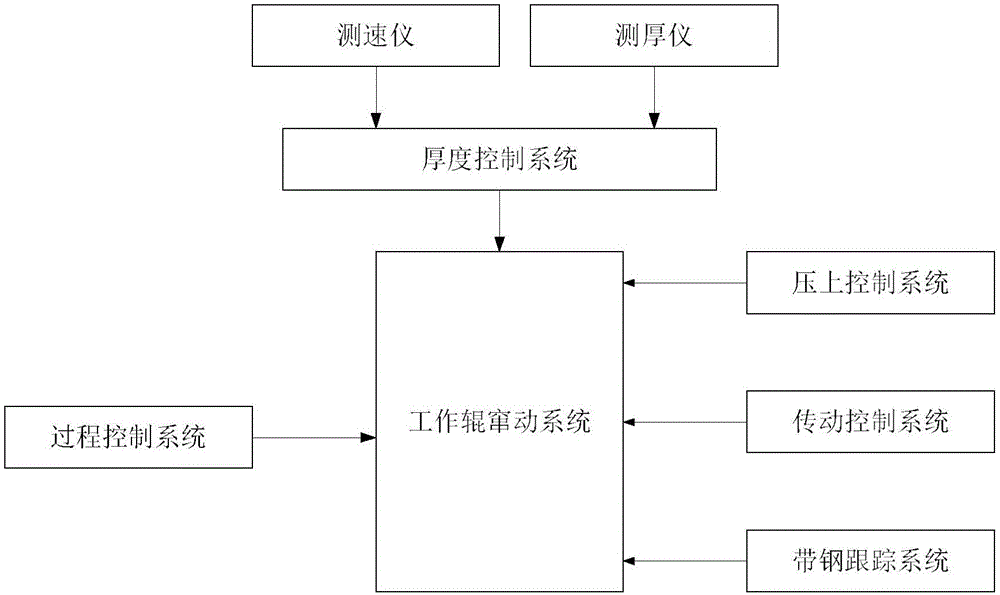
[0082] For the composition of the work roll movement control system, see figure 2 , including the work roll movement system (including the work roll dynamic change specification movement), process control syste...


PUM


Abstract

The invention discloses a dynamic specification-changing moving method for working rollers of a cold continuous mill. When the length L<weld> between a weld of a current roll of strip steel and the next roll of strip steel and a first rack is equal to t<WS>(1).V<0>, the working roller of the first rack starts to move from the current position to the set moving position of the working roller of the next roll of strip steel. When the length L<weld> between the weld of the current roll of strip steel and the next roll of strip steel and the first rack is equal to [t<WS>(2).V<1>-L<12>]H<1>/H<0>, the working roller of a second rack starts to move from the current position to the set moving position of the working roller of the next roll of strip steel. When the length L<weld> between the weld of the current roll of strip steel and the next roll of strip steel and the first rack is equal to [t<WS>(3).V<2>-L<13>]H<2>/H<0>, the working roller of a third rack starts to move from the current position to the set moving position of the working roller of the next roll of strip steel. By means of the dynamic specification-changing moving method, the control precision for thinning of edges of the head and tail of the strip steel can be guaranteed, and the strip steel is prevented from being broken in the positions of welds.

Description

technical field [0001] The invention relates to a method for dynamically changing specification movement of work rolls of a cold tandem rolling mill, which belongs to the field of rolling control. Background technique [0002] The continuous cold rolling production is an endless continuous rolling mode. In order to meet the needs of customers with different product specifications, product specifications are often changed, resulting in different width, steel type and thickness of the current rolling strip and the next coil. Two adjacent coils of strip steel are welded together by a laser welding machine, and a weld seam is formed between the two coils of strip steel. For ordinary four-high rolling mills and six-high rolling mills, since the work rolls are axially fixed, the width, steel type, thickness and other specifications of two adjacent coils of strip can be changed by dynamically adjusting the roll gap, speed and tension when changing specifications. To ensure the sta...

Claims


Application Information

Patent Timeline
IPC IPC(8): B21B28/00
Inventor 刘宝权宋君王奎越金耀辉吴萌李志峰王军生张岩秦大伟侯永刚
Owner ANGANG STEEL CO LTD
Why Eureka
Try Eureka