Elevation type welded pipe unloading device

A lift-type, welded pipe technology, applied in the directions of feeding devices, positioning devices, storage devices, etc., can solve the problems of wasting manpower working time, reducing labor efficiency and work quality, and inaccurate material cutting, so as to improve work efficiency and improve work efficiency. The quality of work, the saving of manual transportation time, the effect of convenient and simple work

Inactive Publication Date: 2017-01-04
启成金属制品(江苏)有限公司
View PDF0 Cites 0 Cited by
  • Summary
  • Abstract
  • Description
  • Claims
  • Application Information

AI Technical Summary

Problems solved by technology

[0002] The cutting machine is a machine that pressurizes the die with the help of the force of the machine movement to cut and process the material. For the cutting equipment with a high degree of automation, the cutting machine includes: a moving head type cutting machine controlled by a computer, a laser cutting machine, etc. Feeder (oscillating cutter), high-pressure water beam cutting machine and computer blanking machine, etc. In addition, Italy and the British USM company produce a projection blanking machine. The blanking table of this equipment is equipped with oscillating cutters and visual The observation device is used to scan the outline of the leather, or project on the leather to guide the blanking worker to arrange the nesting of the blanking template on the leather. Regarding the conventional blanking machine, the conveying material is more complicated, and the working process The inaccurate cutting of the material will affect the subsequent use quality of the material. The manual transportation of the material needs to waste a lot of manpower working time, which reduces the manual work efficiency and work quality; the existing welded pipe cutting device cannot adjust the height and needs to be added on site. High, unable to adapt to the needs of different high and low occasions, affecting work efficiency

Method used


Image

  • Elevation type welded pipe unloading device
  • Elevation type welded pipe unloading device
  • Elevation type welded pipe unloading device

Examples


Embodiment Construction

[0014] The following will clearly and completely describe the technical solutions in the embodiments of the present invention with reference to the accompanying drawings in the embodiments of the present invention. Obviously, the described embodiments are only some, not all, embodiments of the present invention. Based on the embodiments of the present invention, all other embodiments obtained by persons of ordinary skill in the art without making creative efforts belong to the protection scope of the present invention.

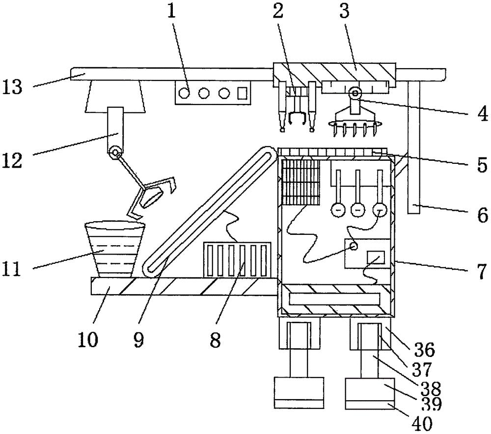
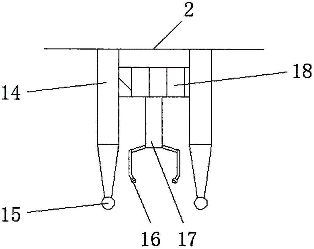
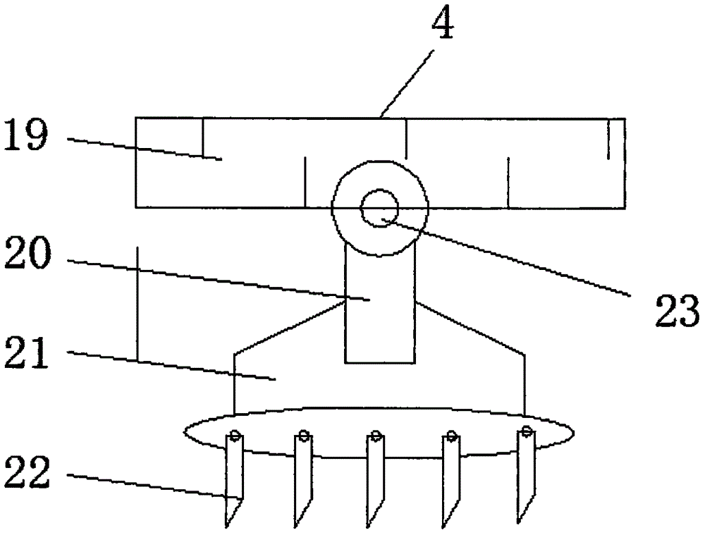
[0015] see Figure 1-4 , an embodiment provided by the present invention: a lifting type welded pipe blanking device, including a working base 10, a working pole 13 and a numerical control main board 25, one end of the working pole 13 is connected with a feeding device 12, and the working pole 13 The other end is inlaid with an inlaid sliding plate 3, and a laser marker 2 is connected under one end of the inlaid sliding plate 3. The laser marker 2 includes a m...


PUM


Abstract

The invention discloses an elevation type welded pipe unloading device, comprising a working bottom plate, a working supporting rod and a numerical control mainboard, wherein feeding equipment is connected to one end of the working supporting rod, an inlaying sliding plate is embedded in the other end of the working supporting rod, a laser marker is connected below one end of the inlaying sliding plate, die cutting equipment is mounted below the other end of the inlaying sliding plate, a working computer case is arranged below the right of the working supporting rod, the numerical control mainboard is arranged at the bottom end of the inside of the working computer case, an electronic speed regulator is arranged above one side of the numerical control mainboard, an equipment driver is mounted above the other side of the numerical control mainboard, the working bottom plate is connected to one side of the outside of the working computer case, a material box is arranged above one end of the working bottom plate, a servo motor is fixed above the other end of the working bottom plate, and a feeding conveyor belt is connected above the servo motor. The elevation type welded pipe unloading device disclosed by the invention can realize automatic feeding and accurate cutting, and is safe and convenient to use.

Description

technical field [0001] The invention relates to the technical field of blanking equipment, in particular to a lifting type welded pipe blanking device. Background technique [0002] The cutting machine is a machine that pressurizes the die with the help of the force of the machine movement to cut and process the material. For the cutting equipment with a high degree of automation, the cutting machine includes: a moving head type cutting machine controlled by a computer, a laser cutting machine, etc. Feeder (oscillating cutter), high-pressure water beam cutting machine and computer blanking machine, etc. In addition, Italy and the British USM company produce a projection blanking machine. The blanking table of this equipment is equipped with oscillating cutters and visual The observation device is used to scan the outline of the leather, or project on the leather to guide the blanking worker to arrange the nesting of the blanking template on the leather. Regarding the convent...

Claims


Application Information

Patent Timeline
Patent Type & Authority Applications(China)
IPC IPC(8): B21D35/00B21C51/00B21D28/02B21D43/02B30B15/26
CPCB21D35/002B21C51/005B21D28/02B21D43/026B30B15/26
Inventor 潘政宇
Owner 启成金属制品(江苏)有限公司
Why Eureka
Try Eureka