Turning equipment

A processing equipment and turning technology, which is applied in the field of mechanical manufacturing and processing, can solve problems such as cracks and deformation, workpiece vibration, and waste of production costs, so as to reduce the probability of fracture, improve processing accuracy, and reduce production costs.

Active Publication Date: 2017-01-04
浙江科锦机电有限公司
View PDF7 Cites 12 Cited by
  • Summary
  • Abstract
  • Description
  • Claims
  • Application Information

AI Technical Summary

Problems solved by technology

[0004] At present, during the turning process of the existing turning processing equipment, the turning tool continuously cuts the workpiece to generate impact, resulting in periodic changes in the cutting force. In this periodic continuous cutting process, it is easy to cause vibration of the workpiece. When the impact and vibration are too large Large or when the two resonate, the surface accuracy and quality of the turned workpiece will be reduced, which will affect the turning efficiency
Moreover, during high-speed cutting, due to the uneven force, the workpiece will be subjected to cold and hot conditions. Under the impact of such force and heat, the workpiece is prone to cracks and deformation, causing the workpiece to be damaged and scrapped, which greatly wastes production. cost
Traditional turning processing equipment also has high requirements on the length of the workpiece. Usually, the workpiece needs to be cut into a reasonable length before turning, which increases the labor cost of workers and reduces the efficiency of workpiece turning.

Method used


Image

  • Turning equipment
  • Turning equipment
  • Turning equipment

Examples


Embodiment Construction

[0032] The turning equipment of the present invention will be further described in detail below in conjunction with the accompanying drawings.

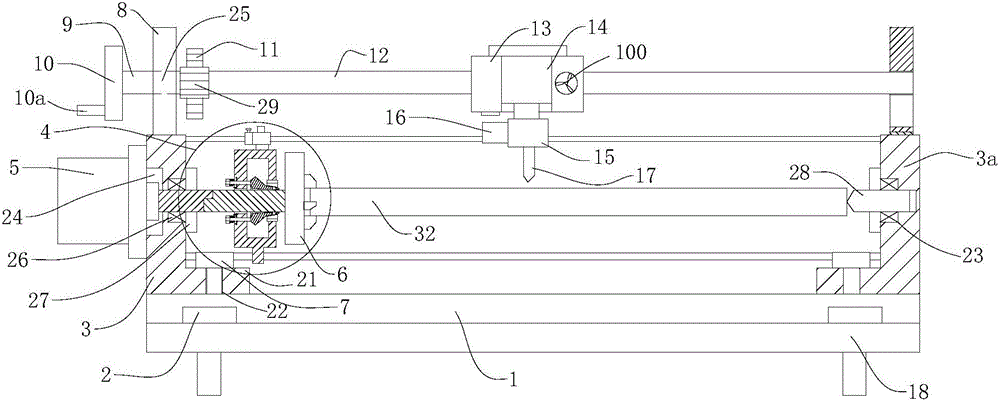
[0033] refer to Figure 1 to Figure 8 The turning processing equipment shown is mainly composed of a base 1, a left frame 3, a right frame 3a and a lathe mechanism. The lathe mechanism includes a moving mechanism and a turning assembly; see Figure 5 As shown, in order to fix the base 1, the base 1 is provided with four anchor bolt holes 19, the base 1 is fixedly connected to the ground through the anchor bolts 2, and the bolts are used to connect and disassemble, which facilitates the moving of the machine in the future. Both sides of the base 1 are also provided with fixed steps 18, that is, both sides of the base 1 are stepped, which facilitates the installation of the anchor bolts 2 on the one hand, and saves the cost of making the base 1 on the other hand. The base 1 is also provided with four screw holes 20, and the left frame ...


PUM


Abstract

The invention provides turning equipment which can be used for turning workpieces with different length and is high in process accuracy and efficiency. The turning equipment comprises a base, a left frame, a right frame and a turning mechanism, and the turning mechanism comprises a moving mechanism and a turning assembly. The moving mechanism comprises a group of a screw seat, a rotary shaft, a hand wheel, a handle, a screw gear and a moving mechanism driven gear which are fixed on the left frame and the right frame respectively and a group of screws which are arranged in parallel. The turning assembly comprises a knife holder, an oil cylinder, a knife rest, a turning motor and a turning tool, the knife rest is assembled on the screws, the oil cylinder is arranged on the knife holder, the knife rest is connected to the output end of the oil cylinder, and the turning motor and the turning tool are mounted on the knife rest. The turning equipment cannot only adaptively adjust the processed installation positions so as to adapt to the workpieces with different length but also can reduce the probability that the surface accuracy of the turning workpieces is low and the fracture probability is high due to ununiform stress in the workpiece turning process.

Description

technical field [0001] The invention relates to the field of mechanical manufacturing and processing, in particular to turning processing equipment. Background technique [0002] Machinery manufacturing refers to the industrial sector engaged in the production of various power machinery, lifting and transportation machinery, chemical machinery, textile machinery, machine tools, tools, instruments, meters and other mechanical equipment. The machinery manufacturing industry is the most basic industry of a country, and it also determines the overall level of a country's manufacturing industry. Its development level directly affects the improvement of the national economic level. [0003] Turning, that is, lathe processing, lathe processing is a part of mechanical processing, mainly using turning tools to turn rotating workpieces. Drills, reamers, reamers, taps, dies and knurling tools can also be used for corresponding processing on the lathe. Lathes are mainly used to proces...

Claims


Application Information

Patent Timeline
Patent Type & Authority Applications(China)
IPC IPC(8): B23B3/00B23B25/06
CPCB23B3/00B23B25/06
Inventor 张俊杰
Owner 浙江科锦机电有限公司
Why Eureka
Try Eureka