Automatic assembly line for feeding, cutting and punching pipe automatically

An automatic feeding and assembly line technology, applied in metal sawing equipment, other manufacturing equipment/tools, metal processing, etc., can solve the problems of high labor intensity, low working efficiency, and skewed cuts in drilling operations

Active Publication Date: 2017-01-04
JIANGSU JINPENG VEHICLE CO LTD
View PDF10 Cites 26 Cited by
  • Summary
  • Abstract
  • Description
  • Claims
  • Application Information

AI Technical Summary

Problems solved by technology

At present, the feeding of pipes is mostly carried out manually. In the process of manual feeding, not only the labor intensity of the workers is high, but also has certain dangers; although there are some mechanical feeding structures, it usually can only realize a single tube. The feeding and conveying of pipes is inefficient
In the process of pipe cutting, most of them are manually cut with a toothless saw cutting machine. This cutting method can only realize the cutting of one pipe at a time. The tooth saw is easy to swing during operation, so this cutting method is likely to cause the incision to be seriously skewed
Since the cutting quality will affect the subsequent welding process, poor cutting quality will result in poor welding quality, which will reduce the qualified rate of the product; at the same time, a large amount of sparks, heat and Noise, which makes the working environment extremely bad, and will bring certain personal injury to the operators in the working environment
The drilling process of the pipe is mostly manual drilling with a bench drill. In the drilling process, usually a phosphating hole needs to be drilled at each end of a pipe, that is, two repeated drillings are required for a pipe. In addition, manual loading and unloading operations are required during the drilling operation, which not only results in high labor intensity and low operating efficiency for the drilling operation, but also lowers the safety of the operator during the drilling operation through the bench drill.

Method used


Image

  • Automatic assembly line for feeding, cutting and punching pipe automatically
  • Automatic assembly line for feeding, cutting and punching pipe automatically
  • Automatic assembly line for feeding, cutting and punching pipe automatically

Examples


Embodiment Construction

[0029] The present invention will be further described below in conjunction with accompanying drawing.

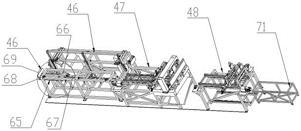
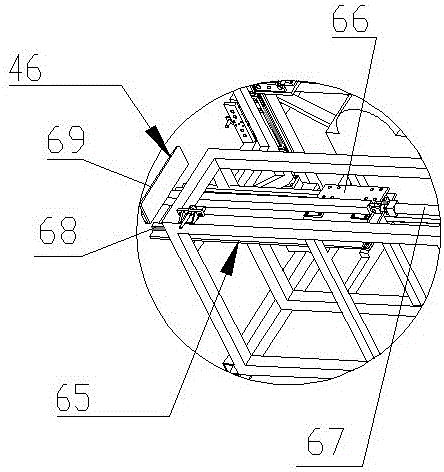
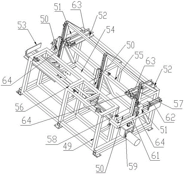
[0030] Such as Figure 1 to Figure 4As shown, an automatic assembly line for automatic feeding, cutting, and punching of pipes includes a front feeding mechanism 46, a middle feeding and cutting mechanism 47, and an automatic punching and unloading mechanism 48 arranged sequentially from left to right. The feeding mechanism 46 includes a first support frame 49, a lifting mechanism 50, a pipe clamping mechanism 51, a widthwise pushing mechanism 52 and a long-term pushing mechanism 53, and the middle part in the width direction of the first support frame 49 is provided with a downwardly recessed Material-lifting channel 54, the first support frame 49 has push zone 55 and feeding zone 56 in the same horizontal plane respectively on the both sides above material-lifting channel 54; The lifting mechanism 50 is made up of a first guide rail 57, a lifting frame 58 and a verticall...


PUM


Abstract

The invention discloses an automatic assembly line for feeding, cutting and punching a pipe automatically. The automatic assembly line comprises a front feeding mechanism, a middle feeding and cutting mechanism and an automatic punching and unloading mechanism which are arranged in sequence from left to right; the front feeding mechanism comprises a first supporting frame, a lifting mechanism, a pipe clamping mechanism, a transverse pushing mechanism and a longitudinal pushing mechanism; the middle feeding and cutting mechanism comprises a second supporting frame, a first clamping conveying mechanism, an automatic cutting mechanism and an automatic clamping mechanism; the automatic punching and unloading mechanism comprises a third supporting frame, a second clamping conveying mechanism, a drilling clamping mechanism and two sliding drilling mechanisms which are positioned on the right side of the second clamping conveying mechanism and are arranged at an interval. The automatic assembly line can realize automatic feeding, and is low in labour intensity and high in work efficiency; the pipe can be cut automatically; the cutting quality is good; high-efficiency cutting operation of one or more pipes can be realized synchronously; the punching operation can be performed on the two ends of the pipe simultaneously; the function of clamping a plurality of pipes at one time and punching the pipes in sequence can be realized.

Description

technical field [0001] The invention relates to pipe cutting equipment, in particular to an automatic assembly line for automatic feeding, cutting and punching of pipes. Background technique [0002] At present, the pipes welded by the electric vehicle frame need to go through three processes of feeding, cutting and drilling. At present, the feeding of pipes is mostly carried out manually. In the process of manual feeding, not only the labor intensity of the workers is high, but also has certain dangers; although there are some mechanical feeding structures, it usually can only realize a single tube. The feeding and conveying of pipes is inefficient. In the process of pipe cutting, most of them are manually cut with a toothless saw cutting machine. This cutting method can only realize the cutting of one pipe at a time. The tooth saw is easy to swing during operation, so this cutting method is easy to cause the incision to be seriously skewed. Since the cutting quality wil...

Claims


Application Information

Patent Timeline
Patent Type & Authority Applications(China)
IPC IPC(8): B23P23/02B23Q7/00B23D47/04
CPCB23D47/04B23P23/02B23Q7/00B23Q7/005B23Q7/06
Inventor 沈伯泽鹿世敏朱红军魏玉强
Owner JIANGSU JINPENG VEHICLE CO LTD
Why Eureka
Try Eureka