
A fence automatic welding device

An automatic welding and fence technology, applied in welding equipment, arc welding equipment, other manufacturing equipment/tools, etc., to achieve the effect of precise hole position, reduced labor intensity, and uniform welding strength

Active Publication Date: 2018-06-19
XINXIANG UNIV
View PDF11 Cites 0 Cited by
  • Summary
  • Abstract
  • Description
  • Claims
  • Application Information

AI Technical Summary

Problems solved by technology

[0003] The technical problem to be solved by the present invention is: the device can quickly open holes on the circumference of the stainless steel pipe wall, and can ensure the accuracy of the hole position; it can quickly weld the connection points between the pipe bodies, and improve the production of the fence. Efficiency and production quality, reduce manual labor intensity

Method used


Image

  • A fence automatic welding device
  • A fence automatic welding device
  • A fence automatic welding device

Examples


Embodiment Construction

[0017] The above solution will be further described below in conjunction with specific embodiments. It should be understood that these examples are used to illustrate the present invention and not to limit the scope of the present invention. The implementation conditions used in the examples can be further adjusted according to the conditions of specific manufacturers, and the implementation conditions not indicated are usually the conditions in routine experiments.

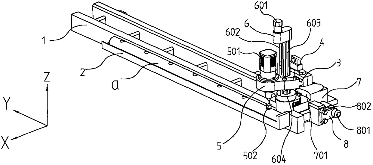
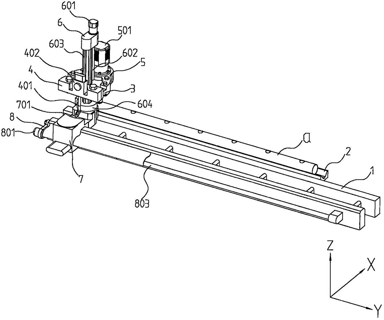
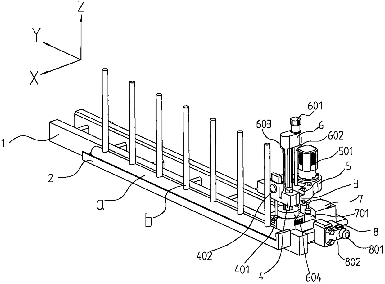
[0018] Such as Figure 1-Figure 3 as shown, figure 1 It is a schematic diagram of the structure of the device provided by the embodiment of the present invention when drilling, figure 2 yes figure 1 Schematic diagram of rear view structure, image 3 It is a structural schematic diagram of the device provided by the embodiment of the present invention during welding.

[0019] In a specific embodiment, a fence automatic welding device is provided, including a guide rail 1, a positioning frame 2, a first mount...


PUM


Abstract

The invention provides an automatic fence welding device, which includes a guide rail, a positioning frame, a mounting frame, a welding device, a drilling device, a steering part, a mounting pallet, a displacement part and a control device. The front end of the guide rail is equipped with a positioning frame and a mounting pallet. There is a placement slot on the top, and a steering part is installed on one end of the top of the mounting plate. The steering part includes a lifting motor, a lifting screw, a spline shaft and a mounting plate. The displacement motor is installed on the guide rail through the mounting bracket. The output shaft end of the displacement motor A displacement screw rod is installed, the displacement screw rod passes through the mounting plate, the displacement screw rod is connected with the mounting plate through a nut, and the displacement screw rod is installed at the rear end of the guide rail. The invention has the advantage of being easy to use, it can facilitate the installation and positioning of the pipe fittings, it is convenient to punch holes on the circumference of the pipe wall, and it can ensure the accuracy of the hole position and avoid the thermal stress generated after manual welding, so the production efficiency of the fence can be improved And production quality, reduce manual labor intensity.

Description

technical field [0001] The invention relates to the welding field, in particular to an automatic fence welding device. Background technique [0002] Fences are widely used in construction and have the functions of safety protection and decoration. The structure of the existing fences is mesh, tubular and plate fences; according to the production materials, it can be divided into stainless steel fences, galvanized fences, painted sheet fences, aluminum alloy fences and wooden fences. Among them, the stainless steel tubular fence has the advantages of light weight, good weather resistance, strong wind resistance and good decorative effect, and is usually installed in public places or on the balcony of buildings. In the production process of the stainless steel tubular fence, holes are opened equidistantly on the circumference of the pipe wall with a larger diameter, then the pipe with a smaller diameter is put into the hole, and finally the connection points are spot welded t...

Claims


Application Information

Patent Timeline
Patent Type & Authority Patents(China)
IPC IPC(8): B23P23/04B23B41/00B23K9/00
CPCB23B41/00B23K9/00B23P23/04
Inventor 李丽陈波张烨程海军王敏
Owner XINXIANG UNIV
Learn More