Laser transmission welding method for connecting plastic pieces

A laser transmission welding and laser welding technology, applied in the field of laser transmission welding, can solve the problems of high instantaneous power, cumbersome actual operation, limited heat transfer efficiency, etc., to achieve the effect of improving heat transfer efficiency, avoiding welding quality, and improving welding quality

Active Publication Date: 2017-01-04
SUZHOU UNIV
View PDF2 Cites 8 Cited by
  • Summary
  • Abstract
  • Description
  • Claims
  • Application Information

AI Technical Summary

Problems solved by technology

The disadvantage of hot plate welding is that the welding process is greatly affected by the environment, and when it is pulled away from the hot plate, it is easy to bond with the plastic to be welded, and the overall welding efficiency is low; hot gas welding mainly depends on the technical level of the operator ; Extrusion welding is due to limited weldable materials and limited scope of application; built-in induction welding and built-in impedance welding are due to the existence of implants, which are not easy to remove after welding, and the existence of inserts will affect the quality of welded joints
[0008] 1. The limitations of the materials to be welded. In most cases, it is necessary to ensure that the light-transmitting parts and the light-absorbing parts exist at the same time, so that they can be melted and bonded in the middle layer. Although additives can solve such problems to a certain extent, the price is relatively High, and the actual operation is cumbersome, not suitable for large-volume, automated production processes
[0009] 2. The scope of application of transmission welding is limited. In industries with special requirements for welding such as medical devices, such as high requirements for appearance, it often cannot meet the requirements
[0010] 3. In the welding process, it mainly depends on the heat transfer between the molten part and the unmelted part, and the heat transfer efficiency is limited
[0011] 4. The shape of the weld seam is difficult to control. It may be due to the unstable light output of the laser, which causes the unevenness of the welding part, and the residual stress after cooling has a significant impact on the welding quality.
[0012] 5. During the welding process, due to the unreasonable setting of the welding parameters, the instantaneous power is too high, burning the plastic parts, and polluting the environment

Method used


Image

  • Laser transmission welding method for connecting plastic pieces
  • Laser transmission welding method for connecting plastic pieces
  • Laser transmission welding method for connecting plastic pieces

Examples


Embodiment Construction

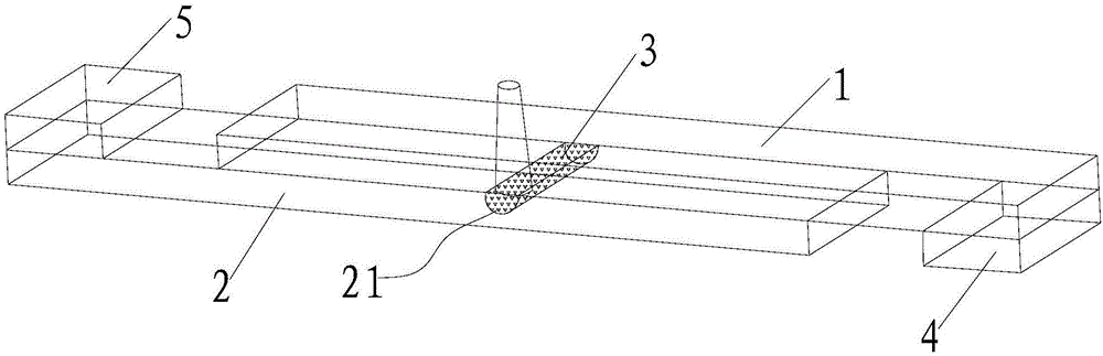
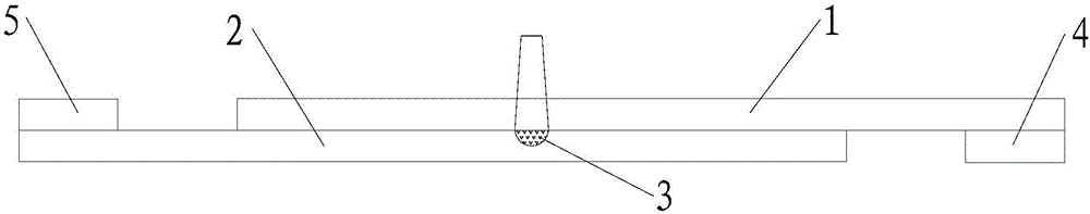
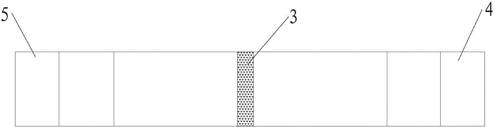
[0032] The technical solutions of the present invention will be further described below in conjunction with the accompanying drawings and specific embodiments.

[0033] see Figure 1 to Figure 3 In the welding working principle diagram shown, the first plastic part 1 and the second plastic part 2 to be welded are both transparent plastic parts, in which the first plastic part 1 is located at the top, the second plastic part 2 is located at the bottom, and the laser is set at the Above a plastic part 1 , the laser beam generated by the laser passes through the first plastic part 1 from above the first plastic part 1 and projects onto the second plastic part 2 . The laser transmission welding is carried out sequentially according to the following steps:

[0034] Firstly, a groove 21 is opened at the position to be welded of the second plastic part 2. The shape of the groove 21 can be determined according to the actual production situation, and its depth is preferably 1mm-2mm. ...


PUM

PropertyMeasurementUnit
depthaaaaaaaaaa

Abstract

The invention discloses a laser transmission welding method for connecting plastic pieces. The method is used for laser welding between a first plastic piece and a second plastic piece; a groove is formed in the second plastic piece, and is filled with zinc alloy powder or similar metal powder with low melting point and high heat conductivity to realize heat transfer, so that the heat transfer efficiency is greatly promoted, and the transmission welding of the same type of plastic pieces can be realized; and in addition, when the light emitting of a laser in unstable, the metal powder achieves an excellent transition effect to prevent influence on the welding quality by higher moment power.

Description

technical field [0001] The invention relates to a laser transmission welding method for connecting plastic parts. Background technique [0002] There are two main welding methods commonly used in plastics and other composite materials: external heating and internal heating. [0003] External heating generally includes hot plate welding, hot gas welding, extrusion welding, built-in induction welding, and built-in impedance welding. The disadvantage of hot plate welding is that the welding process is greatly affected by the environment, and when it is pulled away from the hot plate, it is easy to bond with the plastic to be welded, and the overall welding efficiency is low; hot gas welding mainly depends on the technical level of the operator Extrusion welding is due to limited weldable materials and limited scope of application; built-in induction welding and built-in resistance welding are due to the existence of implants, which are not easy to remove after welding, and t...

Claims


Application Information

Patent Timeline
Patent Type & Authority Applications(China)
IPC IPC(8): B29C65/16
CPCB29C66/1122B29C65/1616B29C65/1635B29C65/168B29C66/43B29K2703/06B29K2705/00B29K2705/02B29K2705/06B29K2705/10
Inventor 王传洋姜宁刘海华陈再良
Owner SUZHOU UNIV
Why Eureka
Try Eureka