

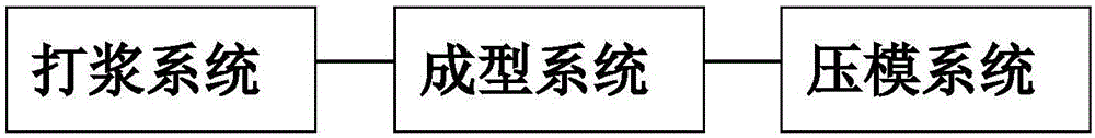
Paper form forming system
A technology of paper molds and forming devices, applied in the field of paper mold forming systems, can solve the problems of small scale and no assembly line, etc., and achieve the effect of good finished products, easy mold release, and high drying degree
- Summary
- Abstract
- Description
- Claims
- Application Information
AI Technical Summary
Problems solved by technology
Method used
Image

Examples
Embodiment 1
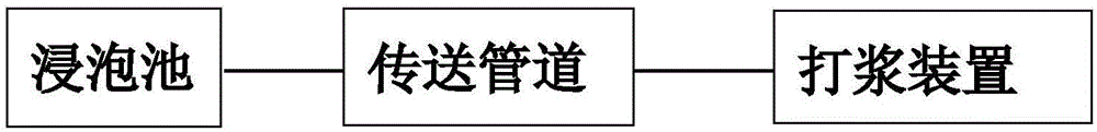
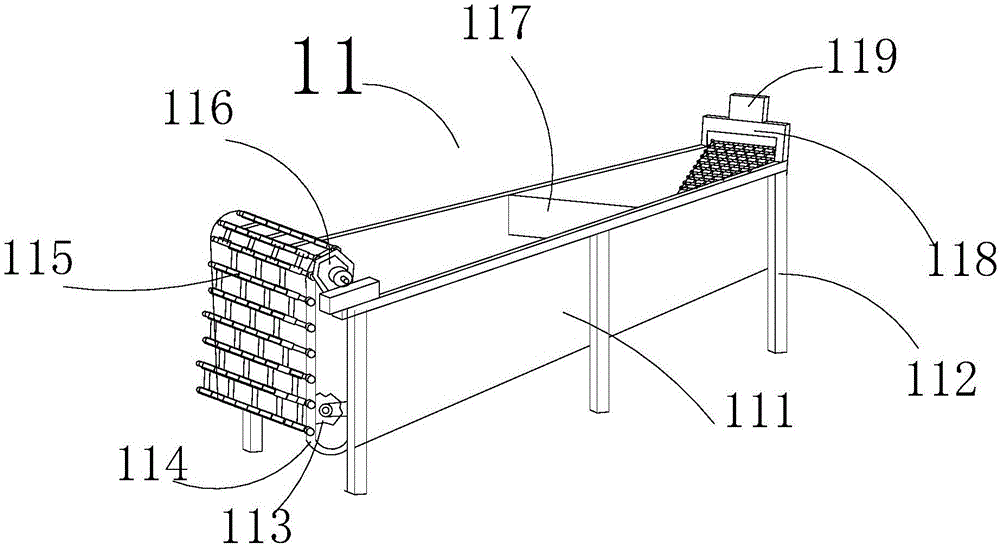
[0033] Such as figure 2 As shown, the beating system includes a soaking tank 11, a transmission pipeline 12 and a beating device 13, the outlet of the soaking tank 11 is connected to the transmission inlet 124 of the transmission pipeline 12, and the transmission outlet 125 of the transmission pipeline 12 is connected to the beating device 13. Material inlet 133, the inside of the soaking tank is provided with a chain surface 115 that can be used as a conveyor belt. The raw material enters the soaking tank and is conveyed to the transmission pipeline 12 through the chain surface 115. The transmission pipeline 12 is equipped with a spiral drive shaft 122, and the raw material is carried out for the first time. Squeeze, shear and transfer to the inside of the beating device 13. The beating device is a double-roller intermeshing beater, which processes the raw materials into pulp that meets the requirements.
[0034] Such as image 3 As shown, the soaking tank includes a soakin...
Embodiment 2
[0044] Such as Figure 7 Figure 8 The forming system shown includes a pulp tank 21, a second control box 24 used to control the overall system outside the pulp tank, a liftable forming device 22 is arranged inside the pulp tank, and the top of the corresponding forming device 22 is fixed by a fixed bracket 26 A transfer device 23, a conveyor belt 25 is provided outside the pulp tank 21, the transfer device 23 can be pulled from the top of the forming device 22 and moved along the X-axis direction to the right above the conveyor belt 25, and the conveying direction of the conveyor belt is perpendicular to the transfer device 23 on the horizontal plane The Y-axis direction of the moving track; the pulp tank is filled with pulp, the forming device 22 descends and immerses in the pulp and then rises to obtain the wet billet prototype, which rises to the corresponding position of the transfer device 23, and the transfer device sucks the wet billet prototype up through vacuum sucti...
Embodiment 3
[0054] Embodiment 3, as the forming system in embodiment 2, the upper surface of the first lifting table 222, the edge of the wet blank mold is provided with a flat groove, and a silk screen is laid in the flat groove to produce a wet blank with an outer eaves.
[0055] The first main control box 243 in the molding system is provided with a control circuit that controls the operation of the whole system and is electrically connected with each part. It is a known technology that has been disclosed and will not be repeated here.
PUM
 Abstract
Description
Claims
Application Information