
Deep mixing pile machine

A technology of deep mixing piles and mixing shafts, which is applied in the direction of sheet pile walls, buildings, and foundation structure engineering, and can solve the problems of increasing the amount and cost of cement slurry, poor embedding effect of support piles, and uneven cement slurry. problems, to achieve the effect of facilitating the spread of slurry, shortening the construction period, and improving the uniformity and compactness

Active Publication Date: 2017-01-04
浙江坤德创新岩土工程有限公司
View PDF6 Cites 5 Cited by
  • Summary
  • Abstract
  • Description
  • Claims
  • Application Information

AI Technical Summary

Problems solved by technology

[0005] The traditional pile driver has the following defects: First, since the spray nozzle is located at the bottom of the mixing head, the essential process of the rotary spraying is to first cut and mix the soil with the blades on the upper part of the spray nozzle, and then spray the cement slurry from the nozzle, but the cement The fluidity of the slurry in the soil is poor, and the deeper the soil layer, the greater the resistance. In addition, the uneven mixing of the blades leads to the inconsistency and unevenness of the cement slurry in the deep layer, which seriously reduces the quality of the pile; in order to improve the quality of the pile, we can only increase the stirring Time and injection pressure, if four agitation and two injections are used, this will inevitably increase the material and cost and prolong the construction period; moreover, the final pile diameter is affected by the injection pressure, the deeper the soil depth, the greater the resistance , so under the same spraying pressure, the diameter of the pile must be large and small, which makes it difficult to control the spraying pressure in the actual rotary spraying process. If the pressure is too high, the amount of cement slurry and the cost will be increased. If the pressure is too small, the overlap between the pile and the pile will not be overlapped or the effect will be poor after the pile is formed. If it is used for a water-stop curtain, it will not have the effect of preventing seepage and water, and if it is used for a support pile, it will be embedded. not effectively

Method used


Image

  • Deep mixing pile machine

Examples


Embodiment Construction

[0014] The present invention will be further described below in conjunction with the accompanying drawings and specific embodiments.

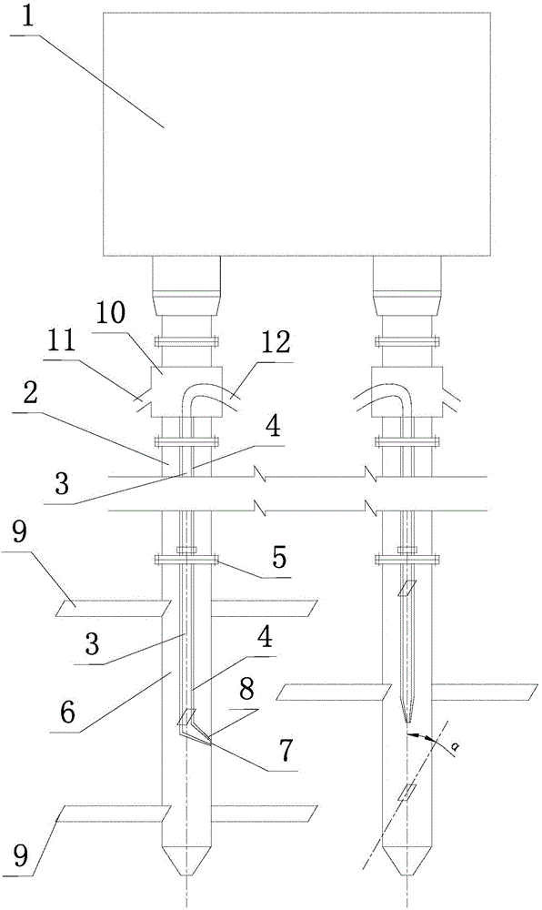
[0015] Such as figure 1 Shown, the deep layer stirring pile driver of the present invention, it comprises pile frame, power head 1, hollow stirring shaft 2, slurry delivery pipe 3, slurry delivery pump, slurry mixer, air delivery pipe 4, air compressor, spray nozzle 7 and Air nozzle 8.

[0016] The power head 1 is installed on the pile frame, the stirring shaft 2 is mounted on the power head 1 and a hollow butt joint 10 is arranged between the stirring shaft 2 and the power head 1 . The lower end of the stirring shaft 2 is fixed with a stirring head 6 through a flange plate 5 . The slurry nozzle 7 and the air nozzle 8 are located in the cavity of the mixing head 6 and the nozzles of the slurry nozzle 7 and the air nozzle 8 all extend out of the mixing head 6 . The air nozzle 8 is sleeved on the outside of the spray nozzle 7 .

[0017] The s...


PUM


Abstract

The invention discloses a deep mixing pile machine. The deep mixing pile machine comprises a power head (1), hollow mixing shafts (2), slurry delivery pipes (3) and air delivery pipes (4). The mixing shafts (2) are installed on the power head (1), and mixing heads (6) are fixed to the lower ends of the mixing shafts (2); slurry nozzles (7) and air nozzles (8) are arranged on the mixing heads (6), the slurry nozzles (7) are sleeved with the air nozzles (8), and the slurry delivery pipes (3) are sleeved with the air delivery pipes (4); at least two sets of blades (9) at different heights are arranged on each mixing head (6), the height positions of the slurry nozzles (7) and the air nozzles (8) are located between the blades (9), the slurry nozzles (7) and the air nozzles (8) are located in the mixing heads (6), jet tips of the slurry nozzles (7) and the air nozzles (8) stretch out of the mixing heads (6), the extension lines of the jet tips of the slurry nozzles (7) and the air nozzles (8) intersect with the blades (9) at the lowermost positions, and the intersection points are located at the tail ends of the blades (9). By means of the pile machine, cement soil for pile forming is dense and uniform, the use level of slurry is lowered, and the pile forming quality is good.

Description

technical field [0001] The invention relates to the construction technology of cement mixing piles in the field of civil engineering, in particular to a deep mixing pile machine. Background technique [0002] With the rapid development of the country's economic construction, especially the widespread rise of housing construction and municipal construction, the construction technology of cement mixing piles is also constantly being developed and applied. Cement mixing piles are mostly used for foundation reinforcement or as support structures and water-stop curtains in foundation pit support systems. [0003] The traditional cement mixing pile machine includes a pile frame, a power head, a hollow stirring shaft, a slurry pipe, a slurry pump, a slurry mixer, an air pipe and an air compressor; the power head is installed on the pile frame, and the stirring shaft is installed on the power head. On the top, a stirring head with blades is fixed at the lower end of the stirring sh...

Claims


Application Information

Patent Timeline
Patent Type & Authority Applications(China)
IPC IPC(8): E02D5/46
CPCE02D5/46E02D2250/003
Inventor 张海滨陈天雄
Owner 浙江坤德创新岩土工程有限公司
Learn More