Rock breaking method

A rock-breaking and rock-breaking machine technology, applied in the field of rock crushing, can solve the problems of ineffective use of machines, increasing the shear force of the rock arm, and low engineering construction efficiency, so as to improve rock-breaking efficiency, enhance stability, reduce The effect of rock breaking energy consumption

Inactive Publication Date: 2017-01-04
凌夕珈
View PDF1 Cites 7 Cited by
  • Summary
  • Abstract
  • Description
  • Claims
  • Application Information

AI Technical Summary

Problems solved by technology

However, in the actual rock breaking process, due to its own characteristics, this type of rock breaking machine has some serious shortcomings, mainly because of poor energy efficiency. Although these equipment can meet the requirements of high, medium and low hardness rock formations, they are not targeted. Strong, resulting in low construction efficiency
Moreover, in the process of rock breaking, the weight of the machine itself cannot be effectively used to increase the cutting force of the rock arm, resulting in a slow rock breaking speed.

Method used


Image

  • Rock breaking method
  • Rock breaking method
  • Rock breaking method

Examples


Embodiment 1

[0044] A rock-breaking method, comprising the steps of:

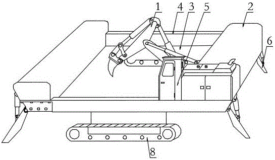
[0045] A. The rock breaker provided with the rock breaking operation area 3 is exercised or moved to the rock breaking area, so that the rock breaking operation area 3 is located above the rock breaking area, and the rock breaking operation area 3 of the rock breaking machine is It is a hollow area that runs through the body of the rock breaking locomotive and is perpendicular to the ground;

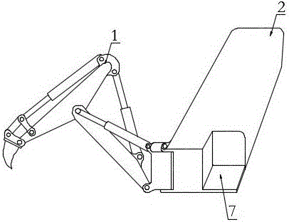
[0046] B. Operate the rock arm 1 to control the rock breaking part on the rock arm 1 to move downward in the rock breaking operation area 3;

[0047] C. The rock breaking part of the rock arm 1 breaks rocks in the rock breaking operation area 3 .

[0048]Wherein, the area of ​​the rock-breaking operation area 3 is set to 7-50 square meters, preferably about 30 square meters, so as to complete a large amount of rock-breaking operations at one time. After the rock-breaking operation area 3 is located above the rock-breaking area, ...

Embodiment 2

[0055] This embodiment is basically the same as Embodiment 1, the main difference is:

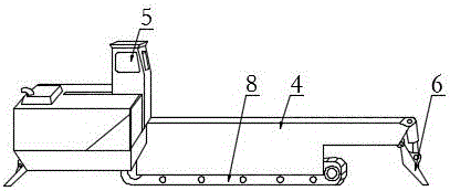
[0056] Described running gear comprises four sets of crawler running gears 8, and each vehicle frame 4 is connected on two sets of crawler running gears 8, and two vehicle frames 4 are respectively symmetrically connected on four sets of crawler running gears 8, and four sets of crawler running gears 8 are all controlled by the control mechanism.


PUM


Abstract

The invention discloses a rock breaking method. The rock breaking method comprises the following steps that A, a rock breaking machine arranged in a rock breaking operation zone is driven or moved to a zone to be subjected to rock breaking, the rock breaking operation zone is made to be above the zone to be subjected, and the rock breaking operation zone of the rock breaking machine is a hollow zone which penetrates through a car body of the rock breaking machine and is perpendicular to the ground; B, a rock arm is operated, and a rock breaking part on the rock arm is controlled to act downwards in the rock breaking operation zone; and C, the rock breaking part of the rock arm breaks rocks in the rock breaking operation zone. The technical effects that the weight of the rock breaking machine can be fully utilized to improve the rock breaking effect of the rock arm in the rock breaking operation zone, and the rock arm is effectively made to conduct rock breaking operation around the gravity center and the nearest zone of the rock breaking machine; and meanwhile, on the premise that the rock breaking effect is ensured, arms with high weight do not need to be lifted, the energy loss of idle work can be reduced to minimum, and thus the rock breaking energy consumption is reduced.

Description

technical field [0001] The invention relates to the field of rock breaking, in particular to a rock breaking method. Background technique [0002] Rock crushing is a process of separating part of the rock mass from the parent body and breaking it into rock blocks during mining operations. There are mainly four types of explosive crushing, mechanical crushing, water jet crushing and thermal crushing in the prior art. in, [0003] Explosive Fragmentation: The use of dynamite or other explosives to instantly release huge energy to break rocks is currently the most widely used and most effective. [0004] Mechanical crushing: divided into four methods: cutting, punching, rolling and grinding. When breaking rock, the rock breaking tool enters the rock, and a dense nucleus appears in the rock body in front of the tool moving. Larger pieces of disintegrated bodies are produced around the dense nucleus. The main reason why mechanical crushing is not widely used in hard rock is s...

Claims


Application Information

Patent Timeline
Patent Type & Authority Applications(China)
IPC IPC(8): E21C27/20E21C29/22E21C47/10
CPCE21C27/20E21C29/22E21C47/10
Inventor 凌夕珈
Owner 凌夕珈
Why Eureka
Try Eureka