Automobile tail gas purifier

A technology for automobile exhaust and purifier, applied in chemical instruments and methods, exhaust treatment, exhaust devices, etc., can solve the problems of limited exhaust purification effect, single purification effect, complex structure, etc., to shorten production time, coating High efficiency and improved catalytic efficiency

Inactive Publication Date: 2017-01-04
WUHU EVERSHINE AUTOMOTIVE COMPONENT
View PDF5 Cites 0 Cited by
  • Summary
  • Abstract
  • Description
  • Claims
  • Application Information

AI Technical Summary

Problems solved by technology

[0005] The technical problem to be solved by the present invention is to provide an automobile exhaust purifier to solve the problems that the current automobile exhaust purifier has a single purifying effect, limited exhaust purifying effect, complex structure and high cost

Method used


Image

  • Automobile tail gas purifier
  • Automobile tail gas purifier

Examples


Embodiment 1

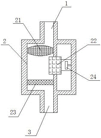
[0025] like Figure 1 to Figure 2 As shown, the present invention provides an automobile exhaust purifier, comprising: an air inlet 1 , a clean chamber 2 communicating with the air inlet 1 , and an air outlet 3 communicating with the clean chamber 2 . Automobile exhaust can enter the purification chamber 2 of the automobile exhaust purifier from the air inlet 1, and be discharged from the air outlet 3 after being purified by the purification chamber 2.

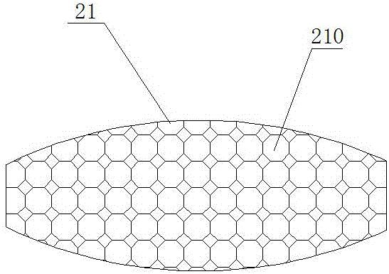
[0026] Specifically, a honeycomb aluminum block 21 is provided near the air inlet 1 inside the clean room 2, and the honeycomb aluminum block 21 has interconnected holes 210, and the walls of the holes 210 are coated with a catalyst, which can remove particulate matter in the exhaust gas. The filter is deposited in the holes 210 of the honeycomb aluminum block 21, and the catalyst covered in the holes 210 is used to catalyze and purify the exhaust gas, which increases the contact surface area between the exhaust gas and the ca...

Embodiment 2

[0028] Catalyst for automobile exhaust gas purifier, including honeycomb aluminum block carrier, pore density is 550cpsi, pore wall thickness is 3.8mil, volume is 0.85L; Pd coating is coated on the honeycomb aluminum block carrier, and the coating amount of Pd coating is 120g / L; the Rh coating is coated on the Pd coating, and the coating amount of the Rh coating is 85g / L; wherein, the Pd content in the Pd coating is 80g / ft 3 , the Rh content in the Rh coating is 15g / ft 3 .

Embodiment 3

[0030] A method for coating and processing catalysts for automobile exhaust purifiers, the steps are as follows:

[0031] ① Coating with Pd coating

[0032] 84g of ZrO 2 , 36g of Pr 6 o 11 , 7.2g La 2 o 3 , 82.8g of γ-Al 2 o 3 , 3g of Zanthoxylum glabrata and an appropriate amount of deionized water are ball milled and mixed, then 5g of palladium nitrate is added and mixed evenly to obtain coating slurry A; then coating slurry A is coated on the honeycomb aluminum block according to the coating amount of 120g / L on the carrier, and finally baked at 650°C for 6 hours to obtain a Pd coating;

[0033] ② Apply Rh coating

[0034] 76.5g of ZrO 2 , 13.5g of Y 2 o 3 , 4g of CeO 2 , 4g of La 2 o 3 , 96g of γ-Al 2 o 3 , 2g of Zanthoxylum glabrata and an appropriate amount of deionized water ball mill and mix, then add 0.5g of rhodium nitrate and mix uniformly to obtain coating slurry B; then apply coating slurry B to the coated The Pd-coated honeycomb aluminum block car...


PUM


Abstract

The invention provides an automobile tail gas purifier which comprises a gas inlet, a purifying chamber communicating with the gas inlet, and a gas outlet communicating with the purifying chamber. A honeycomb aluminum block is arranged in the position, close to the gas inlet, inside the purifying chamber. A three-way catalyst is arranged in the position, close to the gas outlet, inside the purifying chamber. An ozone generator is arranged on one side of a pipeline inside the purifying chamber. Holes communicating with one another are formed in the honeycomb aluminum block. Holes walls of the holes are coated with catalysts. Automobile tail gas is subjected to catalytic purification through the honeycomb aluminum block, the ozone generator and the three-way catalyst in sequence, the purification effect on the tail gas is effectively improved, the structure is simple, and the cost is low.

Description

technical field [0001] The invention relates to the technical field of automobile industry, in particular to an automobile exhaust purifier. Background technique [0002] With the development of the economy and the improvement of people's requirements for the quality of life, the problem of air pollution has become a global issue of great concern. The frequent large-scale smog events in China have put forward higher requirements for air pollution control technology and purification device structure. As the number of domestic automobiles is increasing year by year, automobile exhaust, as one of the important sources of air pollutants, has an important impact on air pollution. [0003] The main components of exhaust gas emitted by automobiles are hydrocarbons, nitrogen oxides, carbon monoxide, and granular carbon. , and the structure is complex and the cost is high. Therefore, it is necessary to provide an automobile exhaust purifier to solve the above problems. [0004] T...

Claims


Application Information

Patent Timeline
Patent Type & Authority Applications(China)
IPC IPC(8): F01N3/035F01N3/08B01J23/63B01J35/04B01J37/02B05D7/14B05D7/24
CPCF01N3/035B01J23/63B01J35/04B01J37/0244B01J2523/00B05D7/14B05D7/24B05D7/544B05D2202/25B05D2451/00B05D2601/20F01N3/08F01N2240/38F01N2250/02F01N2330/02F01N2510/06B01J2523/31B01J2523/36B01J2523/3706B01J2523/3712B01J2523/3718B01J2523/48B01J2523/822B01J2523/824
Inventor 刘华
Owner WUHU EVERSHINE AUTOMOTIVE COMPONENT
Why Eureka
Try Eureka