
A compressor oil pump and frequency conversion compressor

A technology of compressors and oil pumps, applied in the field of compressors, which can solve problems such as high requirements for installation space, high requirements for oil storage, and complex installation and layout structures, and achieve the effect of avoiding load increase

Active Publication Date: 2018-06-01
黄石东贝压缩机有限公司
View PDF7 Cites 0 Cited by
  • Summary
  • Abstract
  • Description
  • Claims
  • Application Information

AI Technical Summary

Problems solved by technology

[0014] The object of the present invention is to provide an oil pump of a compressor and a variable frequency compressor, so as to solve the complex installation arrangement structure, high requirements for installation space, high requirements for oil storage capacity and inability to solve the existing problems of the oil pump and variable frequency compressor of the compressor in the prior art. Realize the adjustment of pump oil capacity and other issues

Method used


Image

  • A compressor oil pump and frequency conversion compressor
  • A compressor oil pump and frequency conversion compressor

Examples


Embodiment 1

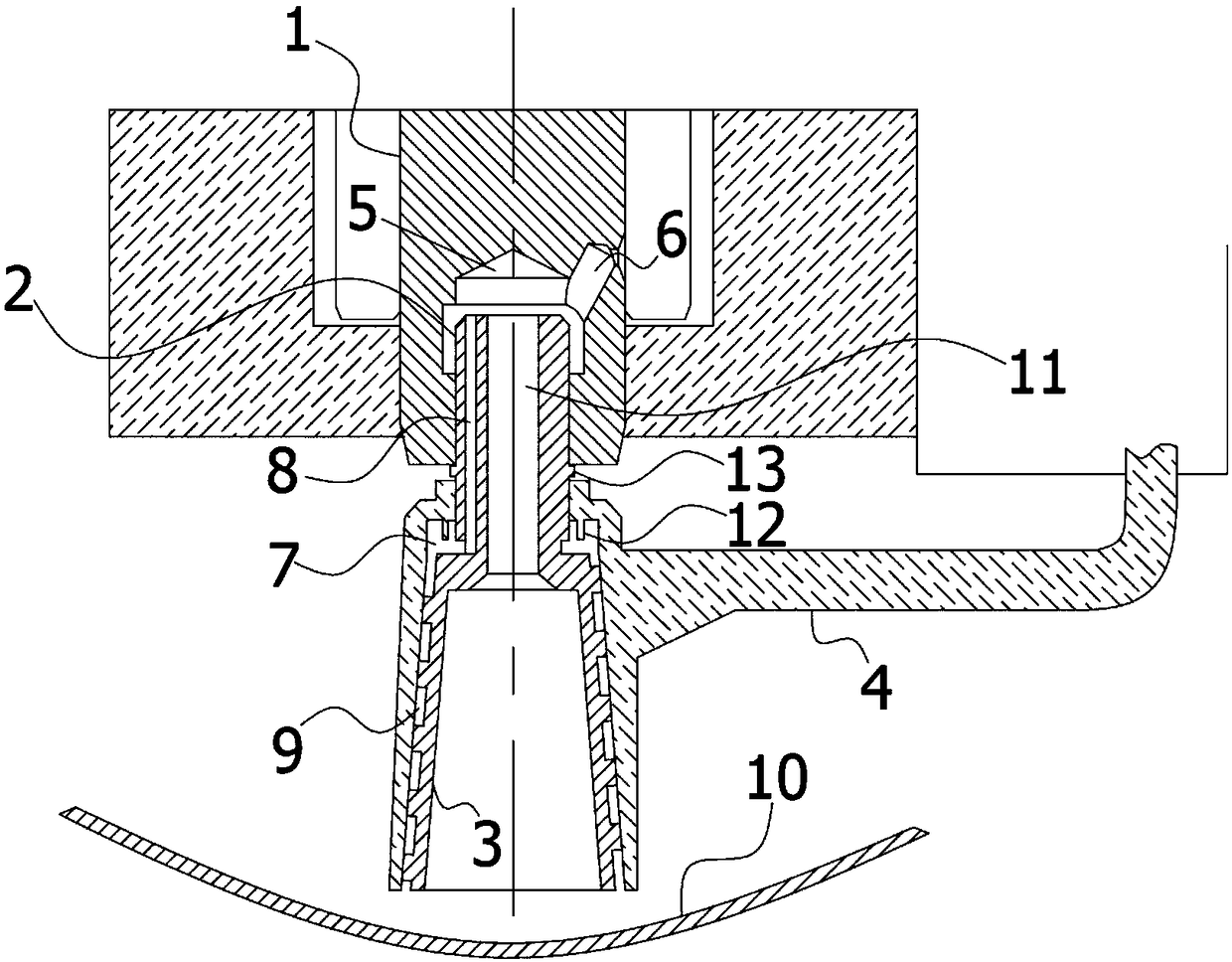
[0064] In the optional scheme of this embodiment, such as figure 1 As shown, further, the lower oil delivery hole 9 is a spiral hole formed by the cooperation between the inner wall of the pump sleeve 4 and the spiral groove provided on the outer wall of the lower mandrel 3 . In this embodiment, the spiral hole is formed by the cooperation between the inner wall of the pump sleeve 4 and the spiral groove provided on the outer wall of the lower mandrel 3. When the lower mandrel 3 rotates, the helical hole can lift the lubricating oil in the oil pool 10 upwards, And at low speed, the oil can be delivered to a higher position.

[0065] In the optional scheme of this embodiment, such as figure 1 As shown, further, the shape of the lower mandrel 3 is a circular truncated body, the diameter of its upper end surface is smaller than the diameter of its lower end surface, and the inner wall of the pump sleeve 4 fits the outer wall of the lower mandrel 3; while the pump sleeve 4 floats...

Embodiment 2

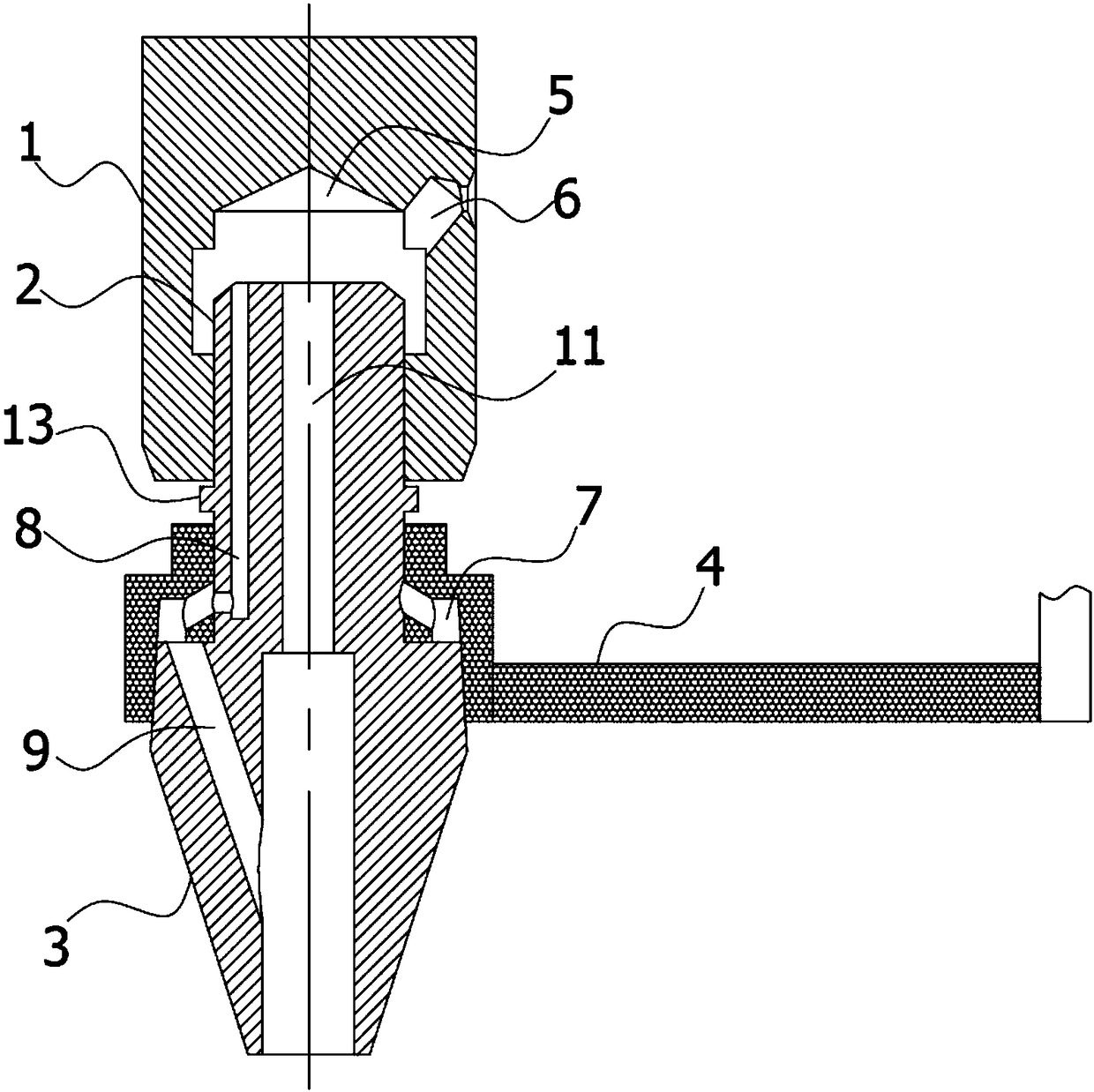
[0067] In the optional scheme of this embodiment, such as figure 2 As shown, further, the lower oil delivery hole 9 is arranged obliquely, communicating with the annular cavity 7 and the oil pool 10 . The lower oil delivery hole 9 is arranged in the lower mandrel 3 body to form a certain inclination angle with the vertical mandrel axis, then the lubricating oil in the oil pool 10 can be introduced into the annular cavity 7 by centrifugal force when the mandrel rotates. The oil pump in this structural form reduces the agitation of the lubricating oil by the part of the outer wall of the lower mandrel 3 immersed in the oil pool, thereby reducing energy consumption and noise.

[0068] In the alternatives of the first and second embodiments, further, an annular groove or a blind hole is provided on the side wall of the slot 5 of the crankshaft 1 . In this embodiment, due to the interference fit between the upper mandrel 2 and the slot hole 5, the elasticity of the material of th...


PUM


Abstract

The invention provides an oil pump of a compressor and a variable frequency compressor. The oil pump comprises a crankshaft, a mandrel and a pump sleeve; the mandrel includes an upper mandrel and a lower mandrel; a groove hole is formed in the lower end surface of the crankshaft; a throttling hole is formed in the side wall of the crankshaft; the pump sleeve is formed with an annular cavity at the connecting part of the upper mandrel and the lower mandrel; an upper oil conveying hole is formed in the side wall of the upper mandrel; a lower oil conveying hole is formed in the lower mandrel; and when the mandrel rotates, lubricating oil can enter a space of the outer side wall of the crankshaft by passing through the lower oil conveying hole, the annular cavity, the upper oil conveying hole, the groove hole and the throttling hole in sequence from an oil pool. The variable frequency compressor is provided with the oil pump. In the oil pump of the compressor and the variable frequency compressor, the mandrel in the oil pump rotates, and the pump sleeve dose not rotate, but moves in the axis direction of the mandrel, so that the oil pumping capacity control of the compressor is realized; and the oil pump has such advantages as simple structure, convenience for installation, lower needed oil storage quantity and lower noise and system influence.

Description

technical field [0001] The invention relates to the technical field of compressors, in particular to an oil pump of a compressor and a variable frequency compressor. Background technique [0002] A compressor is a driven fluid machine that elevates low-pressure gas to high-pressure gas, and is the heart of the refrigeration system. It inhales low-temperature and low-pressure refrigerant gas from the suction pipe, drives the piston to compress it through the operation of the motor, and discharges high-temperature and high-pressure refrigerant gas to the exhaust pipe to provide power for the refrigeration cycle, thereby realizing compression → condensation (heat release ) → Expansion → Evaporation (endothermic) refrigeration cycle. [0003] The structure of the compressor includes cylinder block, rotor, stator, piston, valve plate, connecting rod, crankshaft, end cover and other components. Among them, there are many relatively moving parts, especially the relative moving pa...

Claims


Application Information

Patent Timeline
Patent Type & Authority Patents(China)
IPC IPC(8): F04B39/02
CPCF04B39/0284
Inventor 王道富杨宏林银坤尤琼兵吴其林袁庆庆
Owner 黄石东贝压缩机有限公司
Learn More