Eureka AIR delivers breakthrough ideas for toughest innovation challenges, trusted by R&D personnel around the world.

Elastic blade arranged on top of fan blade, blade provided with elastic blade, and fan

A blade and elastic technology, applied in the field of fan blades, can solve the problems of reduced operating efficiency, reduced air volume and pressure, large blade tip clearance, etc., to achieve the effect of prolonging life, enhancing air volume and wind pressure, and improving operating efficiency

Inactive Publication Date: 2017-01-04
UNIV OF SHANGHAI FOR SCI & TECH
View PDF5 Cites 2 Cited by
  • Summary
  • Abstract
  • Description
  • Claims
  • Application Information

AI Technical Summary

Problems solved by technology

[0004] The present invention is carried out to solve the problem of reduced operating efficiency and significantly reduced air volume and pressure caused by the large blade tip clearance in the above-mentioned axial flow fan, as well as the blade damage caused by friction between the blade and the casing due to the small blade tip clearance. The purpose is to provide a small elastic blade arranged on the top of the blade of an axial flow fan, and a blade and a fan with elastic leaves

Method used


Image

  • Elastic blade arranged on top of fan blade, blade provided with elastic blade, and fan
  • Elastic blade arranged on top of fan blade, blade provided with elastic blade, and fan
  • Elastic blade arranged on top of fan blade, blade provided with elastic blade, and fan

Examples


Embodiment Construction

[0022] In order to make the technical means, creative features, goals and effects of the present invention easy to understand, the following embodiments will specifically illustrate the elastic small blades arranged on the top of the axial fan blades involved in the present invention in conjunction with the accompanying drawings.

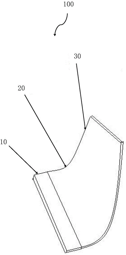
[0023] figure 1 It is a three-dimensional schematic view of the elastic small blade in the embodiment of the present invention;

[0024] Such as figure 1 As shown, the small elastic blade 100 is in the shape of a plate and has a connecting section 10 , a curved section 20 and a free section 30 .

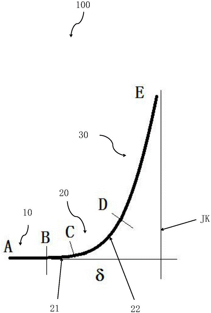
[0025] figure 2 It is a schematic diagram of the longitudinal section of the elastic small blade in the embodiment of the present invention;

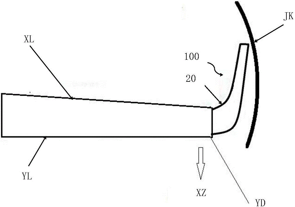
[0026] image 3 It is a schematic diagram of the installation of elastic small blades and fan blades in the embodiment of the present invention.

[0027] Such as figure 2 , image 3 As shown, the longitudin...


PUM


Abstract

The invention relates to an elastic blade arranged on the top of a fan blade, a blade provided with the elastic blade, and a fan. The small elastic blade arranged on the top of the axial flow fan blade is used for reducing the installation interval between the axial flow fan blade and a machine case. The small blade is in the shape of a plate, the longitudinal section of the small blade is L-shaped, the small blade comprises a free section, a connecting section and a bent section, and the bent section faces the suction surface of the axial flow fan blade. By additionally arranging the small blade with certain elasticity on the top of the fan blade, the operation efficiency of the fan, blast capacity and wind pressure are improved due to the fact that the installation interval between the axial flow fan blade and the machine case is reduced. Furthermore, blade damage is avoided even when the small blade with certain elasticity or flexibility collides with or rubs against the machine case. Therefore, the small elastic blade arranged on the top of the axial flow fan blade has the advantage that the operation efficiency of the fan, blast capacity and wind pressure can be improved.

Description

technical field [0001] The invention belongs to the field of machinery, and in particular relates to a fan blade. Background technique [0002] Axial flow fans are generally used for ventilation in factories, warehouses, offices, residences, etc., and can also be used in air coolers (air coolers) and cooling towers. Axial flow fans are mainly composed of impellers, casings, motors and other components. Composition, in large-size axial flow fans such as cooling towers, the tip clearance between the blades of the impeller and the casing is usually relatively large, sometimes up to 30mm, which affects the operating efficiency of the axial flow fan and the air volume and pressure. adverse effects. For axial flow fans, the reduction in operating efficiency due to the large tip clearance may reach more than 5%, and the air volume and pressure will also be significantly reduced. Reducing the blade tip clearance can improve the performance of the fan, but if the clearance is too s...

Claims


Application Information

Patent Timeline
IPC IPC(8): F04D29/38F03D1/06
CPCF03D1/0675F04D29/382F04D29/388Y02E10/72
Inventor 黄典贵
Owner UNIV OF SHANGHAI FOR SCI & TECH
Why Eureka
Eureka Blog
Learn More