Valve core, poppet valve and application of same
A lift valve and spool technology, applied in lift valves, valve operation/release devices, valve details, etc., can solve the problems of high-pressure gas consumption and low efficiency, and achieve simple and easy operation, easy manufacture, and simple appearance Effect
- Summary
- Abstract
- Description
- Claims
- Application Information
AI Technical Summary
Problems solved by technology
Method used
Image
Examples
Embodiment 1
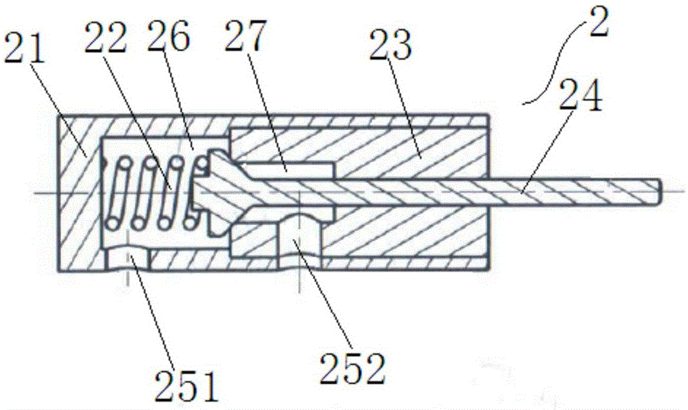
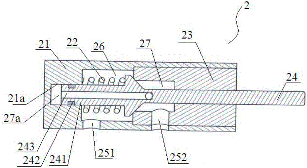
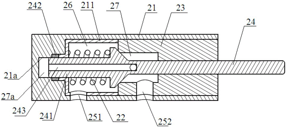
[0055] A spool such as figure 1 As shown, the valve core 2 includes a valve body 21, a valve seat 23, a valve spring 22 and a valve needle 24. After the valve seat 23 is connected with the valve body 21, a front cavity 26 is formed. The valve spring 22 is arranged in the front cavity 26, and one end thereof Press on the valve body 21 , and the other end presses on the tail end of the valve needle 24 passing through the valve seat 23 to provide the pre-pressure of the valve needle 24 on the valve seat 23 . The valve needle 24 can slide in the valve seat 23 , and the valve seat 23 is provided with a rear cavity 27 . Two fluid ports are opened on the valve body 21 , the first fluid port 251 is in constant communication with the front cavity 26 , the second fluid port 252 is in constant communication with the rear cavity 27 , and the tail end of the valve needle 24 is provided with a protrusion. When the valve needle 24 is at the rightmost end, the protrusion is in close contact ...
Embodiment 2
[0060] A poppet valve such as Figure 4 ~ Figure 6 As shown, it includes a cam assembly 1, a rocker arm assembly and any valve core in Embodiment 1. There are two rocker arm assemblies, respectively the main rocker arm assembly 3 and the auxiliary rocker arm assembly 4, and the main rocker arm assembly 3 and the auxiliary rocker arm assembly 4. The auxiliary rocker arm assemblies 4 are respectively arranged on opposite sides of the cam assembly 1, and there are 5 spools 2 in total, among which, 3 spools 2 connected with the main rocker arm assembly 3 are provided, which are connected with the auxiliary rocker arm assembly 4 The spool 2 is provided with two. Wherein the cam assembly 1 and the rocker arm assembly are located inside the valve body 5 which is composed of a cam box 51 and a cam box cover 52 .
[0061] Such as Figure 7 , Figure 8 As shown, the cam assembly 1 includes a main shaft 11, a first cam 12, a second cam 13, a third cam 14 and a fourth cam 15, the first...
Embodiment 3
[0074] The poppet valve described in Example 2 is used in a vascular expander, and its structure is as follows Figure 14 As shown, there are three spools 2 connected to the main rocker arm assembly 3, wherein the second fluid port 252 of the left spool 2 is connected to the air reservoir 621, the first fluid port 251 is connected to the vessel 61, and the middle valve The first fluid port 251 of the core 2 is connected to the gas reservoir 622, the second fluid port 252 is connected to the vessel 61, the first fluid port 251 of the valve core 2 on the right is connected to the gas reservoir 623, and the second fluid port 252 is connected to the vessel 61 connections.
[0075] There are two spools 2 connected to the auxiliary rocker arm assembly 4, wherein the second fluid port 252 of the left spool 2 is connected to the low-pressure outlet pipeline 632, the first fluid port 251 is connected to the vessel 61, and the right valve The first fluid port 251 of the core 2 is conne...
PUM
 Abstract
Description
Claims
Application Information
 - R&D
- Intellectual Property
- Life Sciences
- Materials
- Tech Scout
- Unparalleled Data Quality
- Higher Quality Content
- 60% Fewer Hallucinations
Browse by: Latest US Patents, China's latest patents, Technical Efficacy Thesaurus, Application Domain, Technology Topic, Popular Technical Reports.
© 2025 PatSnap. All rights reserved.Legal|Privacy policy|Modern Slavery Act Transparency Statement|Sitemap|About US| Contact US: help@patsnap.com


