A remote-controlled magnetic rotating chandelier

A technology of magnetic rotation and chandeliers, which is applied in lighting auxiliary devices, lighting and heating equipment, fixed lighting devices, etc., can solve problems such as poor user experience, inability to rotate at will, single structure of chandeliers, etc., to save materials and increase safety , the effect of reducing the volume of the space

Active Publication Date: 2019-07-23
中山市两益照明有限公司
View PDF5 Cites 0 Cited by
  • Summary
  • Abstract
  • Description
  • Claims
  • Application Information

AI Technical Summary

Problems solved by technology

But the traditional chandelier has a single structure and cannot be rotated at will. If you want to adjust the irradiation range, you have to disassemble the whole chandelier, which is very inconvenient
At the same time, the existing chandelier has a single function and poor user experience. In order to improve these problems, the present invention proposes a new technical solution

Method used


Image

  • A remote-controlled magnetic rotating chandelier
  • A remote-controlled magnetic rotating chandelier
  • A remote-controlled magnetic rotating chandelier

Examples


Embodiment Construction

[0027] Embodiments of the present invention are described in detail below, examples of which are shown in the drawings, wherein the same or similar reference numerals represent the same or similar elements or elements having the same or similar functions throughout.

[0028] In the description of the present invention, it should be noted that for orientation words, such as the term "center", "horizontal (X)", "longitudinal (Y)", "vertical (Z)", "length", "width ", "Thickness", "Top", "Down", "Front", "Back", "Left", "Right", "Vertical", "Horizontal", "Top", "Bottom", "Inner" , "Outside", "Clockwise", "Counterclockwise", etc. indicating orientation and positional relationship are based on the orientation or positional relationship shown in the drawings, and are only for the convenience of describing the present invention and simplifying the description, rather than indicating or implying The devices or elements must have a specific orientation, be constructed and operated in a ...


PUM


Abstract

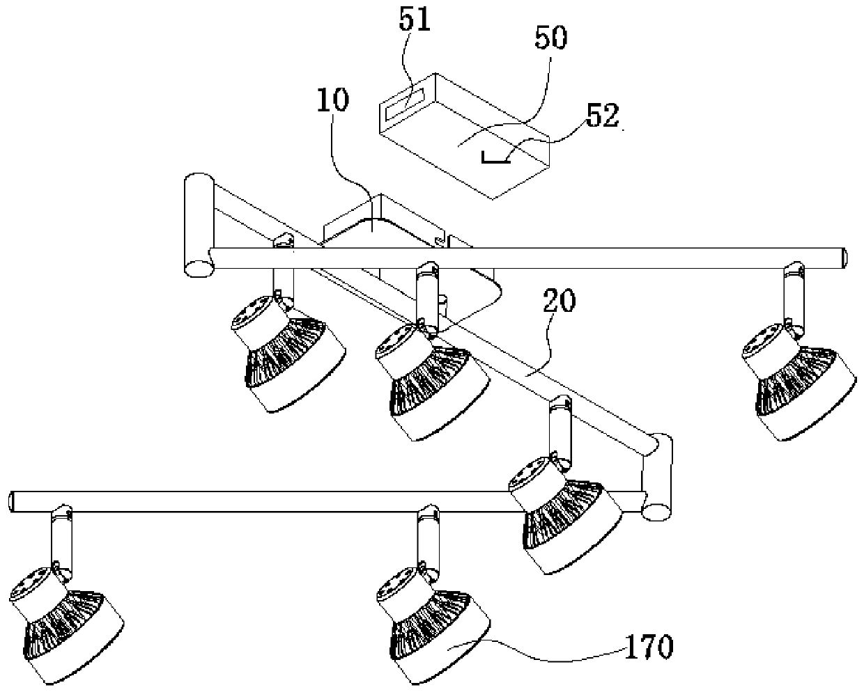
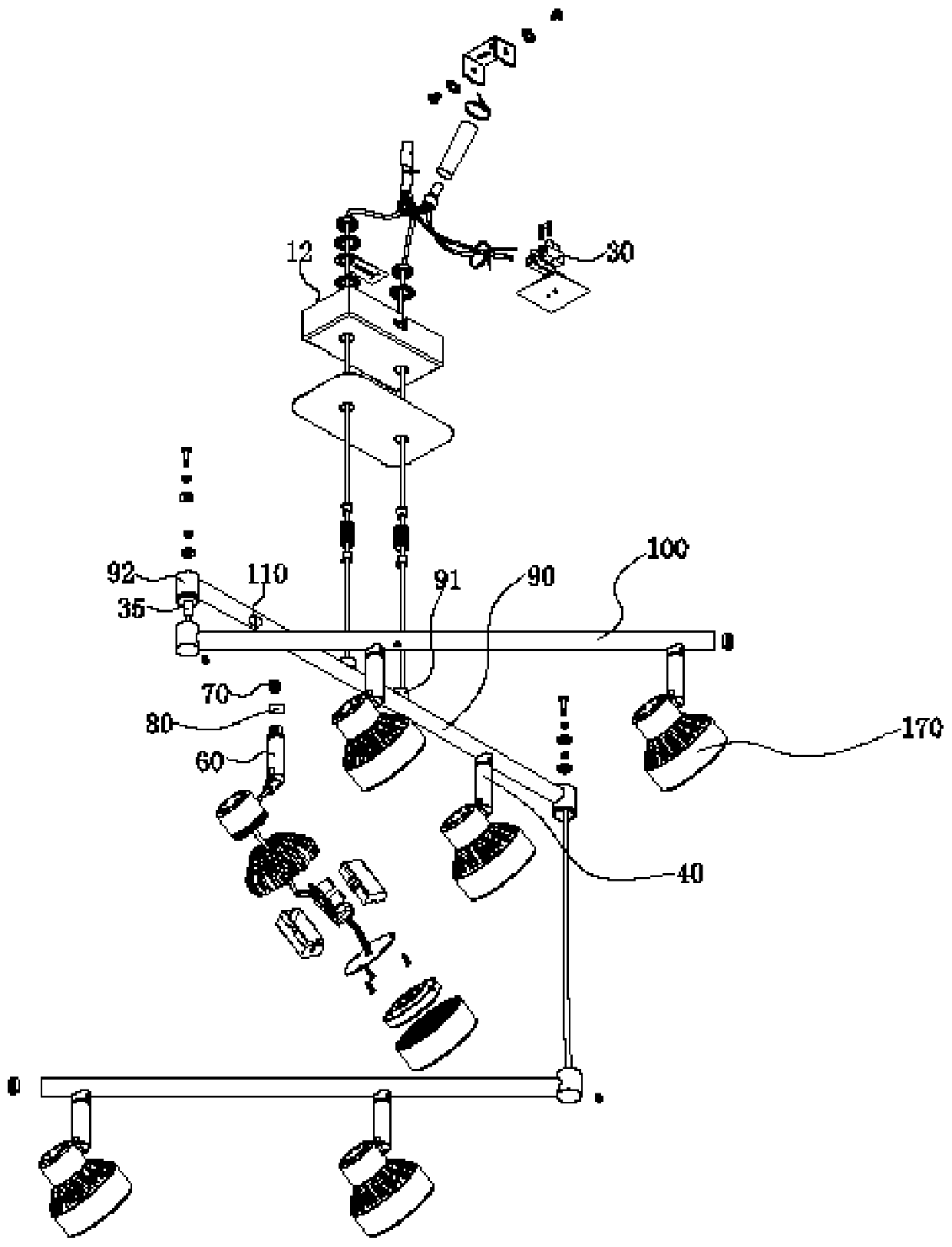
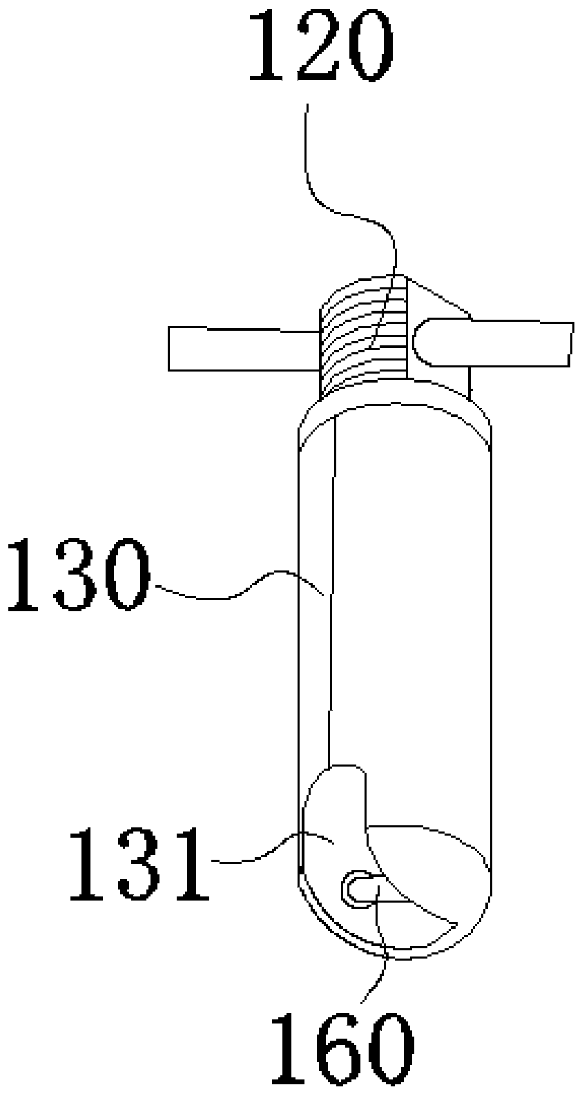
The invention discloses a remotely-controlled magnetic spinning pendant lamp. The remotely-controlled magnetic spinning pendant lamp comprises a hanging bracket and a lamp pole, wherein the side face of the hanging bracket is provided with a plurality of bent positions; the hanging bracket is provided with a cavity; a remote control switch device is arranged in the cavity; a magnetic spinning device is arranged on the lamp pole; the magnetic spinning device comprises a magnetic spinning lamp shaft, winding coils and a brushless electronic speed controller; the lamp pole comprises a main lamp pole and a rotating lamp pole; both the main lamp pole and the rotating lamp pole are provided with a plurality of magnetic spinning holes; the winding coils are placed in the magnetic spinning holes; a connector protrudes out of the top end of the main lamp pole; the main lamp pole is fixed to the hanging bracket through the connector; the two ends of the main lamp pole are provided with rotating parts; permanent-magnet synchronous motors are arranged in the rotating parts; the end part of the rotating lamp pole is fixedly connected to the permanent-magnet synchronous motors. The remotely-controlled magnetic spinning pendant lamp is simple in structure, is convenient to use, and saves more materials and is lower in production cost than an ordinary fixture; compared with the conventional pendant lamp, the remotely-controlled magnetic spinning pendant lamp has the advantages that the irradiation range can be enlarged through rotating lamplight, a fantasy feel is brought to people in conjunction with lamplight of different colors, and the mood of people is improved.

Description

[0001] 【Technical field】 [0002] The invention mainly relates to a remote-controlled magnetic rotating pendant lamp. [0003] 【Background technique】 [0004] In daily life, chandeliers are very popular. People use chandeliers in homes, restaurants, and shopping malls to install chandeliers on the ceiling to facilitate lighting and decoration at the place to be decorated or illuminated. With the widespread application, chandeliers have penetrated into all aspects of our daily life, and can be seen in living rooms, bedrooms, restaurants, guest rooms, shopping malls and other occasions in hotels. However, the structure of the traditional chandelier is single and cannot be rotated arbitrarily. It is very inconvenient to disassemble the entire chandelier if the irradiation range is to be adjusted. At the same time, the existing chandelier has a single function and poor user experience. In order to improve these problems, the present invention proposes a new technical solution. ...

Claims


Application Information

Patent Timeline
Patent Type & Authority Patents(China)
IPC IPC(8): F21S8/06F21V21/30F21V21/15F21V21/02F21V23/04
CPCF21S8/06F21V21/02F21V21/15F21V21/30F21V23/0435
Inventor 魏均
Owner 中山市两益照明有限公司
Why Eureka
Try Eureka