Eureka AIR delivers breakthrough ideas for toughest innovation challenges, trusted by R&D personnel around the world.

Temperature monitoring device

A technology of monitoring device and supporting device, applied in the direction of measuring device, thermometer, temperature measurement in motor, etc., can solve the problems of inability to sense windings, capacitive coupling interference, high installation expenses, etc., to improve load utilization, The effect of reducing the overall size and reducing the installation space

Inactive Publication Date: 2017-01-04
EBM PAPST MULFINGEN GMBH & CO KG
View PDF2 Cites 0 Cited by
  • Summary
  • Abstract
  • Description
  • Claims
  • Application Information

AI Technical Summary

Problems solved by technology

In this case it may not be possible to reliably sense the hottest point of the winding that has overheated
Also, especially in frequency-controlled motors, the capacitive coupling between the temperature sensor and the motor winding can be disturbed because the link current is delivered through the temperature sensor line
[0010] In addition, the incorporation of thermal sensors or sensors in the windings creates a high installation outlay and necessitates an early shutdown of the motor in the event of a fault due to the large temperature differences between the windings involved and the circuit board , which in turn leads to motor load problems due to too small a load factor

Method used


Image

  • Temperature monitoring device
  • Temperature monitoring device
  • Temperature monitoring device

Examples


Embodiment Construction

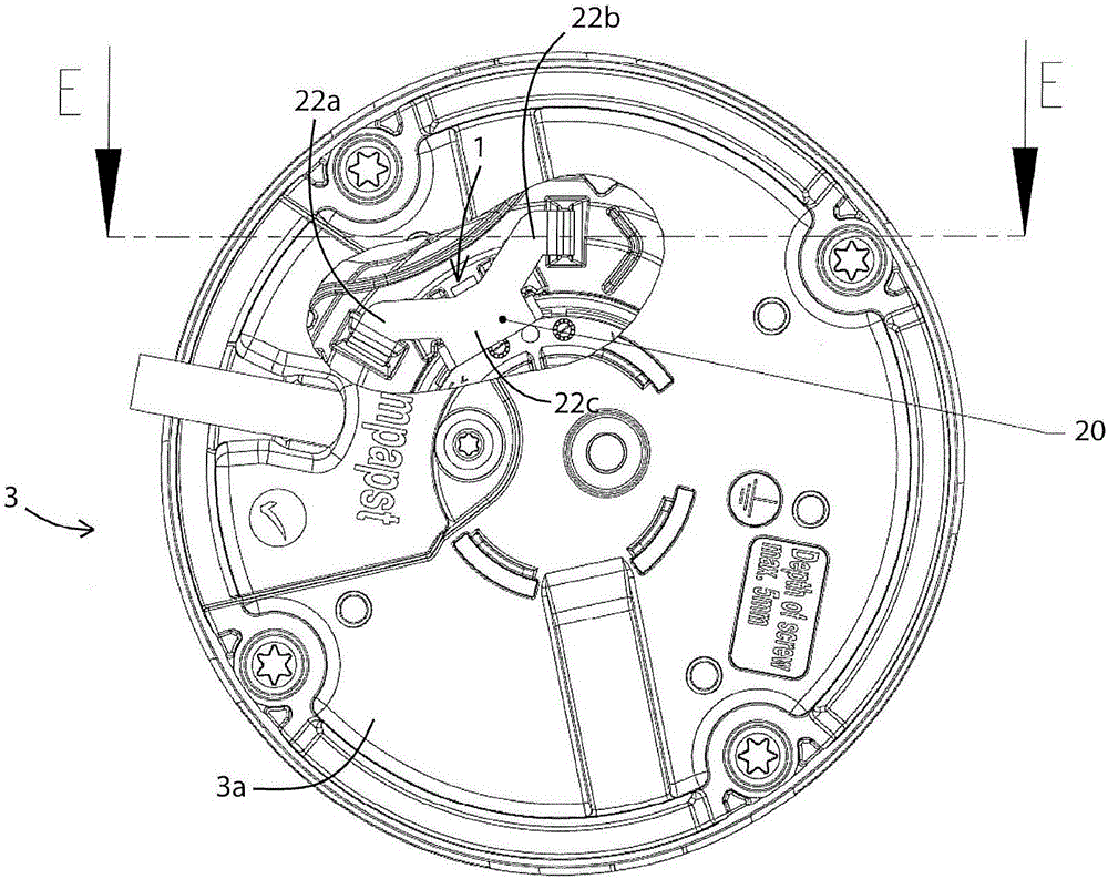
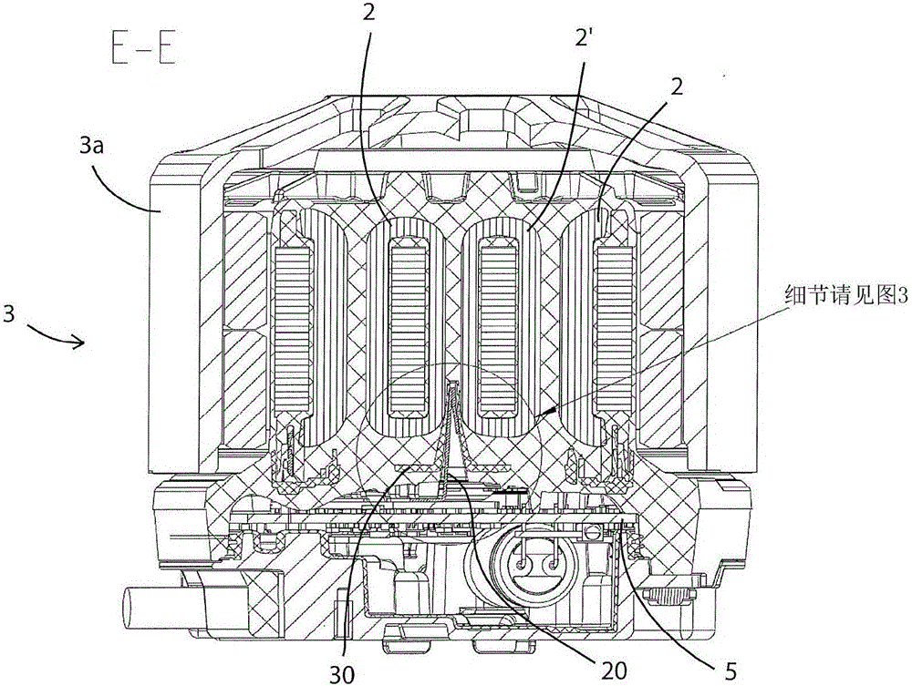
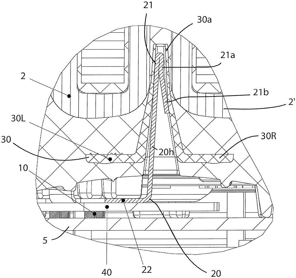
[0028] Contact below Figure 1 to Figure 3 , the invention is described with the aid of exemplary embodiments, wherein identical structural features or functional features are indicated by identical symbols.

[0029] figure 1 and figure 2 An electric motor 3 is shown comprising a temperature monitoring device 1 for monitoring the windings 2, 2' of the electric motor 3.

[0030] image 3 Shown are details of a temperature monitoring device 1 comprising a temperature sensor 10 spaced apart from the windings 2, 2' of the motor 3 and a heat conduction assembly 20, wherein the heat conduction assembly 20 is connected from it for thermal coupling and heat conduction to A first component part 21 , in which the windings 2 , 2 ′ are in contact or adjacent, extends to a second component part 22 , which is in contact with or adjacent to the temperature sensor 10 for thermal coupling and heat conduction.

[0031] figure 1 A view from below of the electric motor 3 is shown, wher...


PUM


Abstract

The invention relates to a temperature monitoring device (1) for monitoring the windings (2, 2 ') of a motor (3), comprising at least one temperature sensor (10) or thermal switch (10') arranged outside and spaced apart from the windings (2, 2 ') of the motor, at least one heat-conducting component (20) which extends from a first component section (21) contacted with or adjacent to the windings (2, 2 ') for heat coupling and heat transfer to a second component section (22) contacted with or adjacent to the temperature sensor (10) for heat coupling and heat transfer. The temperature monitoring device can be realized at a low cost, the overall installation space is reduced, the load utilization of the motor is improved, and moreover, the temperature monitoring device accurately senses the temperature of the motor winding that can not be tolerated so that the motor can be turned off before or during the occurrence of thermal overload.

Description

technical field [0001] The invention relates to a temperature monitoring device for monitoring motor windings, and a motor provided with such a temperature monitoring device. Background technique [0002] In electric drives and electric motors heat loss in the electric motor is almost unavoidable. The motor thus has an upper temperature limit, as soon as it is exceeded, for example due to insulation failure of the windings, the motor can be damaged or stop running. [0003] Inadmissibly high temperatures can occur inside the motor due to malfunctions of the drive or the motor itself. Such situations can occur under pre-set conditions of high machine load, for example when running unevenly or when the mechanical structure is blocked. Dirty ventilation grilles on the motor can also cause an undesired temperature increase. If the motor windings exceed the allowable temperature, the motor will be damaged and the entire machine may stop. Therefore, in order to prevent the mot...

Claims


Application Information

Patent Timeline
Patent Type & Authority Applications(China)
IPC IPC(8): G01K7/00H02K11/25G01K13/00
CPCG01K7/00G01K2205/00H02H7/0852H02H7/0833H02K11/25G01K1/12G01K1/14
Inventor W·霍夫曼S·多伊布勒H·力波T·海利
Owner EBM PAPST MULFINGEN GMBH & CO KG
Why Eureka
Eureka Blog
Learn More