Composite material spring and manufacturing method thereof

A composite material and manufacturing method technology, applied in the direction of high internal friction springs, etc., can solve the problems of heavy self-weight, poor corrosion resistance of metal springs, influence of use time, etc., to reduce weight, improve load utilization, excellent toughness and The effect of resilience

Active Publication Date: 2020-12-29
TIANJIN POLYTECHNIC UNIV
View PDF9 Cites 0 Cited by
  • Summary
  • Abstract
  • Description
  • Claims
  • Application Information

AI Technical Summary

Problems solved by technology

Metal springs have poor corrosion resistance and require anti-corrosion treatment and regular maintenance. The service life is seriously affected. Compared with metal springs, composite material springs have the advantages of light specific gravity, high modulus, high specific strength, and corrosion resistance. Most of the composite material springs that have appeared are helical springs or leaf springs. The fiber direction of these types of springs is not the same or close to the direction of the force, and the high load-bearing capacity in the fiber direction of the composite material cannot be fully utilized, resulting in self-weight Heavy weight, unable to meet the growing demand for ultra-light components in the aerospace industry

Method used


Image

  • Composite material spring and manufacturing method thereof
  • Composite material spring and manufacturing method thereof
  • Composite material spring and manufacturing method thereof

Examples


Embodiment Construction

[0032] Embodiments of the present invention will be described in detail below in conjunction with the accompanying drawings.

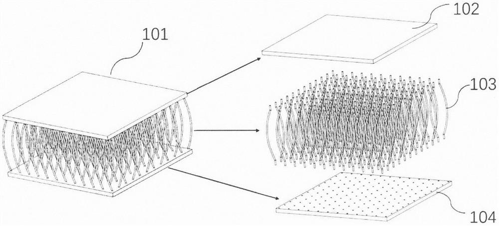
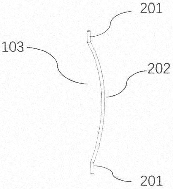
[0033] The prefabricated part of the first embodiment of the present invention is a composite material rectangular spring 101. The part 101 is divided into three parts: an upper panel 102, a lower panel 104, and a middle spring wire 103. The upper and lower panels 102, 104 have a size of 80× 80mm, thickness 1.5mm. Spring wire 103 total length is 38mm, and its up and down straight section 201 is long 2mm, and middle part curved section 202 is long 34mm, and spring wire 103 section is circular, and its diameter is 0.8mm, and the spacing between spring wire 103 and spring wire 103 is 7mm. The rectangular spring 101 in this embodiment has 12 rows of spring wires 103 in total, and there are 12 in one row. The odd-numbered row of spring wires 103 are uniformly bent to the right, and the even-numbered row of spring wires 103 are uniformly bent to the left. Th...


PUM

PropertyMeasurementUnit
lengthaaaaaaaaaa

Abstract

The invention relates to a composite material spring, and particularly relates to an ultra-light composite material spring with a bent rod structure and a manufacturing method thereof. The composite material spring is characterized in that the spring structure comprises an upper panel, a lower panel and spring wires, wherein one side, facing the spring wires, of each panel is provided with a holeor a groove into which the spring wires can be inserted to play a role in fixing; the spring wires are made of a continuous fiber composite material; each spring wire has a C-shaped slender rod structure and comprises straight sections and a bent section along the length direction; the two ends of each spring wire are the straight sections, and the middle part of each spring wire is the bent section; the bent section is used for deforming and providing a reacting force; the extending directions of the straight sections at the two ends are the same as the fiber length directions of the spring wires; and the number of the spring wires in the spring is more than 3. The bearing direction of the composite material spring is basically the same as the fiber directions of the spring wires, so thatthe bearing force of fibers is fully utilized, the load utilization rate of the material is increased, and the weight of the spring can be reduced to a great extent.

Description

technical field [0001] The invention relates to the field of composite material springs and the manufacture thereof, in particular to a composite material spring with an ultra-light non-helical structure in the shape of a bent rod and a manufacturing method thereof. Background technique [0002] At present, new energy, national defense, chemical industry, aerospace, semiconductor and other cutting-edge special fields have increasingly stringent requirements on the performance of springs. Metal springs have poor corrosion resistance and require anti-corrosion treatment and regular maintenance. The service life is seriously affected. Compared with metal springs, composite material springs have the advantages of light specific gravity, high modulus, high specific strength, and corrosion resistance. Most of the composite material springs that have appeared are helical springs or leaf springs. The fiber direction of these types of springs is not the same or close to the direction...

Claims


Application Information

Patent Timeline
Patent Type & Authority Applications(China)
IPC IPC(8): F16F3/10
CPCF16F3/10
Inventor 王晓旭石妍李睿龙罗晋吉
Owner TIANJIN POLYTECHNIC UNIV
Why Eureka
Try Eureka